Supercharge Your Innovation With Domain-Expert AI Agents!

Automatic buoy identification system based on multi-beam infrared sector scanning space detection

An automatic identification system and sector scanning technology, applied in the field of buoy identification, can solve the problems of environmental illumination changes, shadows, occlusion and other factors, large observation errors, complex equipment and other problems, to achieve convenient and reliable acquisition, improve recovery efficiency, and degree of automation high effect

Inactive Publication Date: 2018-05-29
HUAZHONG UNIV OF SCI & TECH
View PDF3 Cites 1 Cited by
  • Summary
  • Abstract
  • Description
  • Claims
  • Application Information

AI Technical Summary

Problems solved by technology

Conventional positioning systems include global positioning system (GPS), Wi-Fi technology, ultra-wideband (UWB) technology, and radio frequency identification (RFID) technology. Among them, the global positioning system is composed of 24 orbiting satellites and receivers carried by targets Network, realize navigation and positioning function, apply the GPS technology in outdoor measurement, not only the equipment is complex, expensive, but also will produce serious multipath effect; Wi-Fi technology, ultra-wideband (UWB) technology, radio frequency identification (RFID) technology It is a commonly used indoor positioning technology. Using these technologies outdoors, especially in marine environments, will cause large observation errors, complex algorithms, and are susceptible to environmental lighting changes, shadows, occlusions and other factors.

Method used


Image

  • Automatic buoy identification system based on multi-beam infrared sector scanning space detection
  • Automatic buoy identification system based on multi-beam infrared sector scanning space detection
  • Automatic buoy identification system based on multi-beam infrared sector scanning space detection

Examples


Embodiment Construction

[0035] In order to make the object, technical solution and advantages of the present invention clearer, the present invention will be further described in detail below in conjunction with the accompanying drawings and embodiments. It should be understood that the specific embodiments described here are only used to explain the present invention, not to limit the present invention. In addition, the technical features involved in the various embodiments of the present invention described below can be combined with each other as long as they do not constitute a conflict with each other.

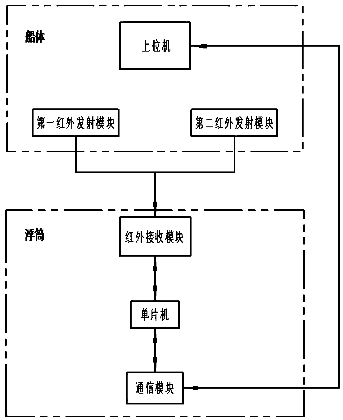
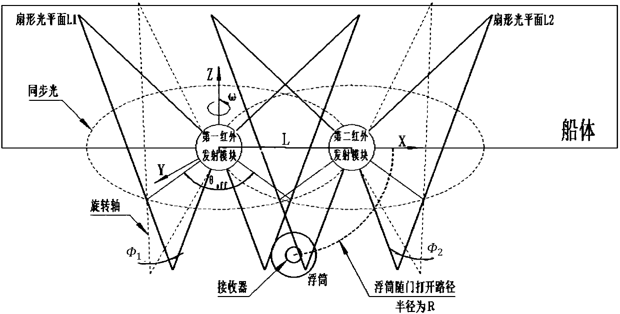
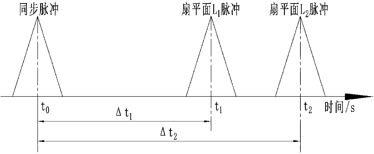
[0036] Such as figure 1 As shown, the embodiment of the present invention provides a buoy automatic identification system based on multi-beam infrared sector scanning space detection, which includes an infrared emitting unit and an infrared receiving unit, wherein the infrared emitting unit is used to emit infrared light, and the infrared receiving unit is used to It is used to receive infrared...


PUM


Abstract

The invention, which belongs to the technical field of buoy identification, specifically discloses an automatic buoy identification system based on multi-beam infrared sector scanning space detection.The system is composed of an infrared transmitting unit and an infrared receiving unit. The infrared transmitting unit consists of a first infrared transmitting module and a second infrared transmitting module that are arranged at the same side of a ship body at an interval and is used for generating infrared light successively. The infrared receiving unit is installed on a buoy includes an infrared receiving module, a single-chip microcomputer and a communication module; the infrared receiving module is used for collecting time difference data of scanning of the two infrared transmitting modules when the first infrared transmitting module and the second infrared transmitting module carry out scanning one after another and sending the data to the single-chip microcomputer; the single-chipmicrocomputer receives the time difference data, converts the time difference data into real-time spatial position signal data of the buoy, and sends the data to the communication module; and the communication module sends the real-time spatial position signal data of the buoy to an upper computer. Therefore, automatic identification of the buoy is realized; and the recognition accuracy and the applicability are high.

Description

technical field [0001] The invention belongs to the technical field of buoy identification, and more specifically relates to an automatic identification system for buoys based on multi-beam infrared fan-shaped scanning space detection. Background technique [0002] With the rapid development of maritime oil transportation, the number of ship oil spill accidents has also increased significantly. The frequent occurrence of marine oil spill accidents will not only pollute the marine ecological environment, but also bring serious harm to the world's ecological environment and affect the sustainable development of the entire human race. develop. [0003] At present, there are physical methods, chemical methods and biological methods for recovering oil spills. In comparison, mechanical oil skimmers using physical methods are the most recognized in the industry. Over the years, dozens of oil skimmers have been developed and born one after another. The built-in brush-belt oil recov...

Claims


Application Information

Patent Timeline
Patent Type & Authority Applications(China)
IPC IPC(8): G01S5/16G06F17/15
CPCG01S5/16G06F17/15
Inventor 陈良洲张广丰宋畅陈有林金磊
Owner HUAZHONG UNIV OF SCI & TECH
Features
  • R&D
  • Intellectual Property
  • Life Sciences
  • Materials
  • Tech Scout
  • Unparalleled Data Quality
  • Higher Quality Content
  • 60% Fewer Hallucinations
Learn More