Device and method for applying flowable material to substratum that can be rotated about axis of rotation

A technology of flowing material and rotating axis, applied in metal processing equipment, additive processing, additive manufacturing, etc., can solve the problems of easy interference, complex structure and slow printing speed of the print head device

Active Publication Date: 2018-05-29
3D系统有限公司
View PDF7 Cites 2 Cited by
  • Summary
  • Abstract
  • Description
  • Claims
  • Application Information

AI Technical Summary

Problems solved by technology

The structure of the known device is complex and is susceptible to interference, especially due to the movably arranged print head arrangement
Geometric distortions and inhomogeneities may be present in the printed image
Stitching is practically infeasible because there are so many small print heads
Also, the printing speed is very slow due to the time required for moving the print head assembly

Method used


Image

  • Device and method for applying flowable material to substratum that can be rotated about axis of rotation
  • Device and method for applying flowable material to substratum that can be rotated about axis of rotation
  • Device and method for applying flowable material to substratum that can be rotated about axis of rotation

Examples


Embodiment Construction

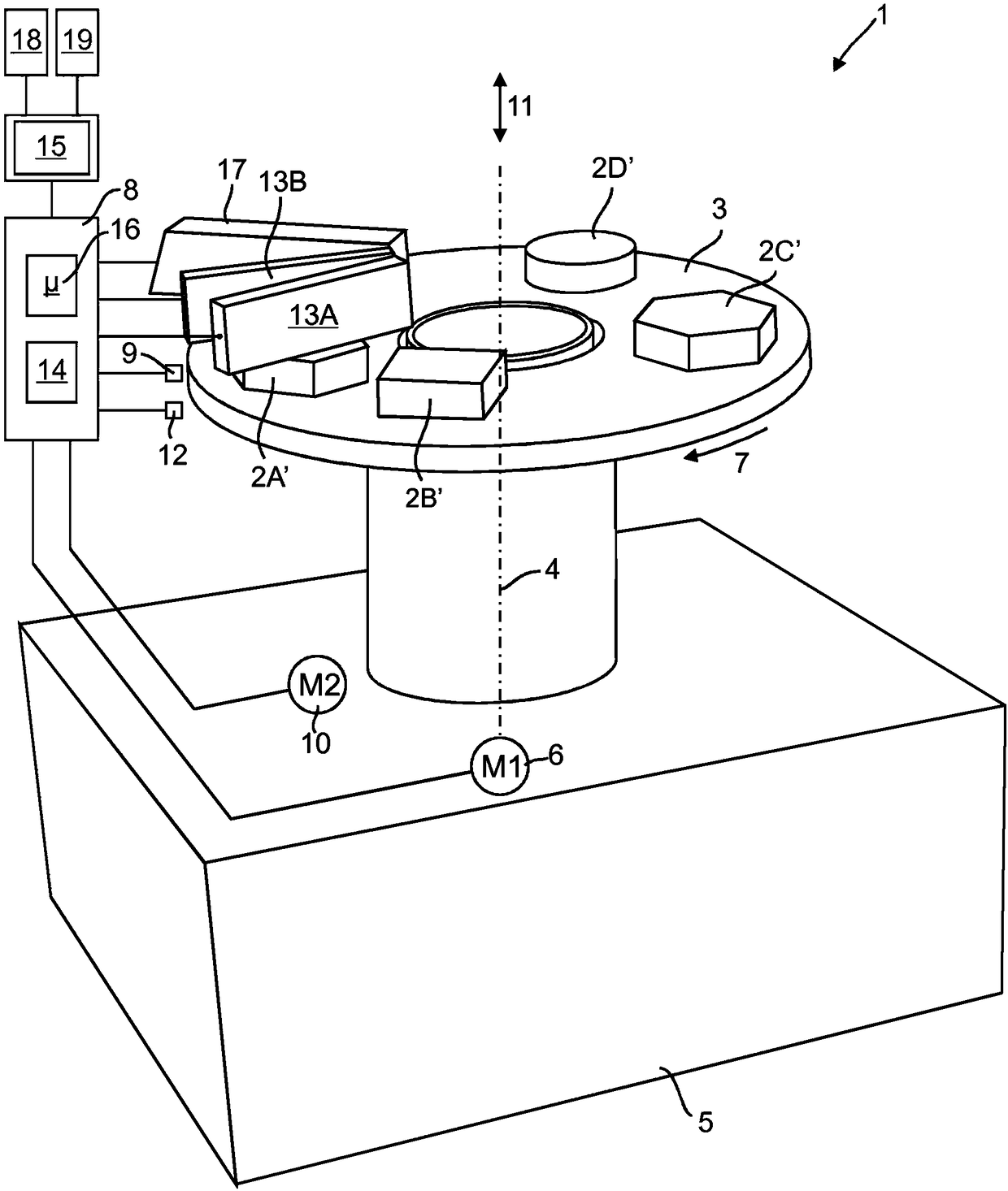
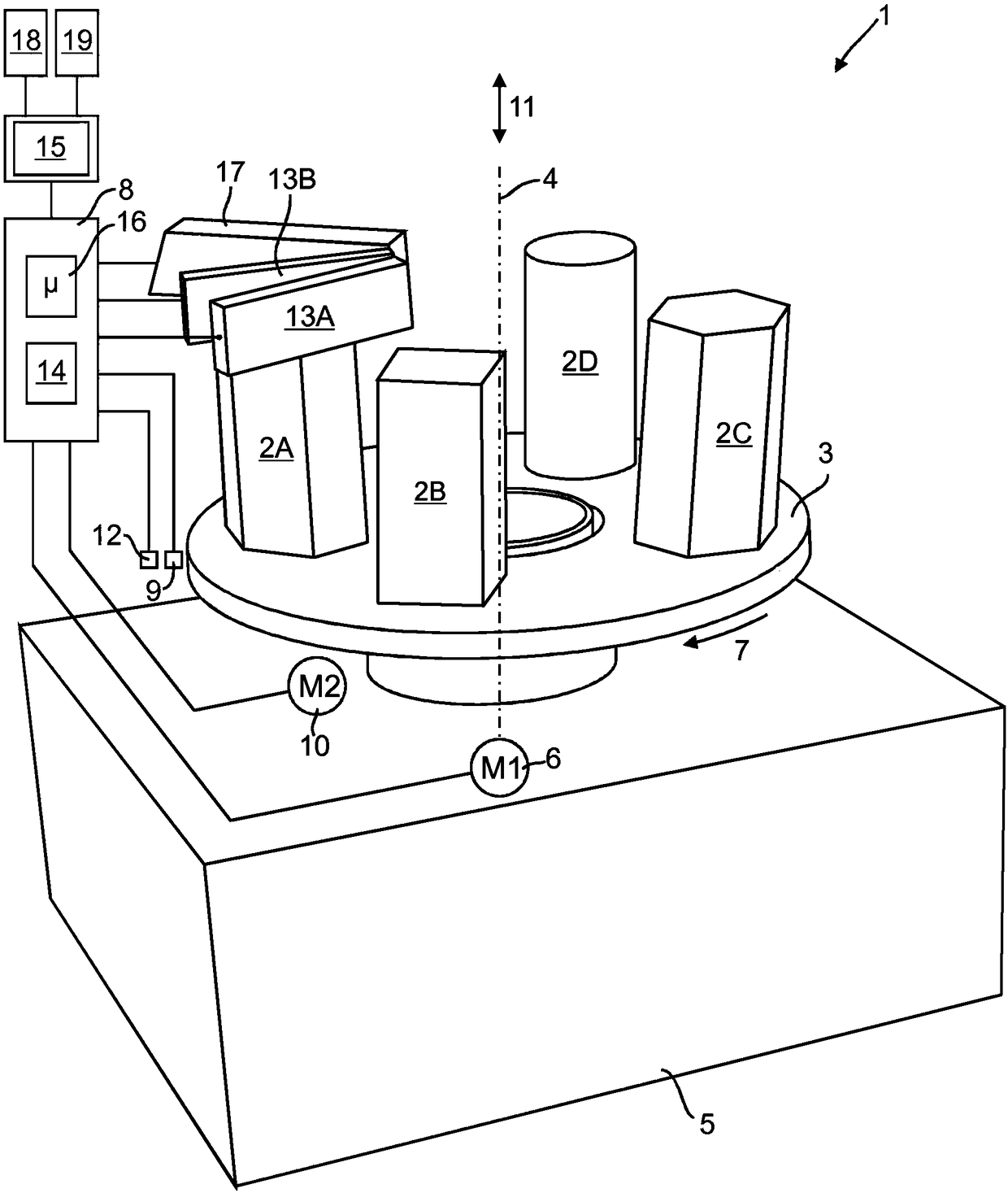
[0054] exist figure 1 The device for the production of three-dimensional shaped objects 2A, 2B, 2C, 2D by means of the layer-by-layer application of material, identified as a whole by 1, has a planar base 3 which extends in a horizontal plane. Layer stacks 2A', 2B', 2C', 2D' can be applied to the base 3 for a plurality of shaped objects 2A, 2B, 2C, 2D, each having a plurality of material layers.

[0055] The base 3 is designed as an annular turntable, which is mounted torsionably about a vertical axis of rotation 4 on a stationary holding device 5 . On its underside, the holding device 5 has a mounting surface by means of which it can be installed, for example, on a tabletop or on the floor of a space.

[0056] The base 3 is in driving connection with a first positioning device having a first drive motor 6 by means of which the base 3 can be driven in rotation in the direction of the arrow 7 and according to the rotation provided by the operating device 8 position - desired ...


PUM


Abstract

The invention relates to a device for applying flowable material to a substratum (3), which can be rotated about an axis of rotation (4), in accordance with specified image data, which are stored as pixels or as vectors of a certain Cartesian coordinate grid in a first memory (18), has at least one printing head (13A, 13B), which has a plurality of nozzles arranged at a nozzle distance from each other for discharging material drops of the flowable material and is arranged at a vertical distance from the substratum, and a controller (8) for positioning the substratum (3) in relation to the at least one printing head (13A, 13B) and the discharge of the material drops. In a second memory (19), particular polar coordinate grid points (20A, 20B) of a certain polar coordinate grid are stored, which polar coordinate grid points are arranged on circular lines (R1, R2) having a predetermined circular-line distance from each other and are arranged on first rays (A1), which have a first angular distance from each other and are arranged in the direction of origin on further rays (A2) having an angular distance from each other that is greater than the first angular distance. A computer (15) ispresent, by means of which the particular polar coordinate grid points (20A, 20B) stored in the second memory (19) can be transformed into coordinates of the certain Cartesian coordinate system and the Cartesian grid points thus obtained are compared with the pixels of the image file.

Description

technical field [0001] The invention relates to a device for applying a flowable material to a base rotatable about an axis of rotation according to preset image data stored as pixels or vectors of a specific Cartesian coordinate system in a first In memory, the device has at least one printhead having a plurality of nozzles arranged relative to each other at a nozzle pitch to output material droplets of a flowable material, and the printheads are vertically spaced relative to A base is provided, and the apparatus has control means for positioning the base relative to the at least one printhead and for outputting droplets of material. [0002] Furthermore, the invention relates to a method for applying a flowable material to a base rotatable about an axis of rotation according to preset image data stored as pixels or vectors of a specific Cartesian coordinate system in In a first reservoir, wherein material droplets of a flowable material are applied to the base by means of a...

Claims


Application Information

Patent Timeline
Patent Type & Authority Applications(China)
IPC IPC(8): B29C64/112B29C64/386B29C64/209B33Y30/00B33Y50/02
CPCB33Y30/00B33Y50/02B29C64/112B29C64/393B29C64/176B29C64/209B29C64/241B29C64/245B29C64/386B33Y10/00G05B19/4099G05B2219/36565G05B2219/49007G06V10/751
Inventor H·玛西亚
Owner 3D系统有限公司
Why Eureka
Try Eureka