
Cooling device in rotating drum core part for preventing latex bonding in concentration and separation process

A cooling device and separation process technology, applied in the direction of centrifuges, etc., can solve the problems of separation effect decline, material clogging, etc., and achieve the effects of avoiding generation and growth, improving quality, reducing space occupation and complex structure

Pending Publication Date: 2018-06-01
ZHEJIANG QINGJI IND +1
View PDF1 Cites 1 Cited by
  • Summary
  • Abstract
  • Description
  • Claims
  • Application Information

AI Technical Summary

Problems solved by technology

[0003] The object of the present invention is to solve the problem of latex solidification and ball cap formation due to the temperature rise of the drum core and the bottom drum during the latex concentration and separation process, resulting in a decline in the separation effect and material clogging. Cooling liquid is fed into the core to effectively cool down the core and bottom surface of the drum and prevent the drum core from sticking during the latex concentration and separation process.

Method used


Image

  • Cooling device in rotating drum core part for preventing latex bonding in concentration and separation process
  • Cooling device in rotating drum core part for preventing latex bonding in concentration and separation process
  • Cooling device in rotating drum core part for preventing latex bonding in concentration and separation process

Examples


Embodiment Construction

[0024] The technical solutions of the present invention will be further specifically described below through the embodiments and in conjunction with the accompanying drawings.

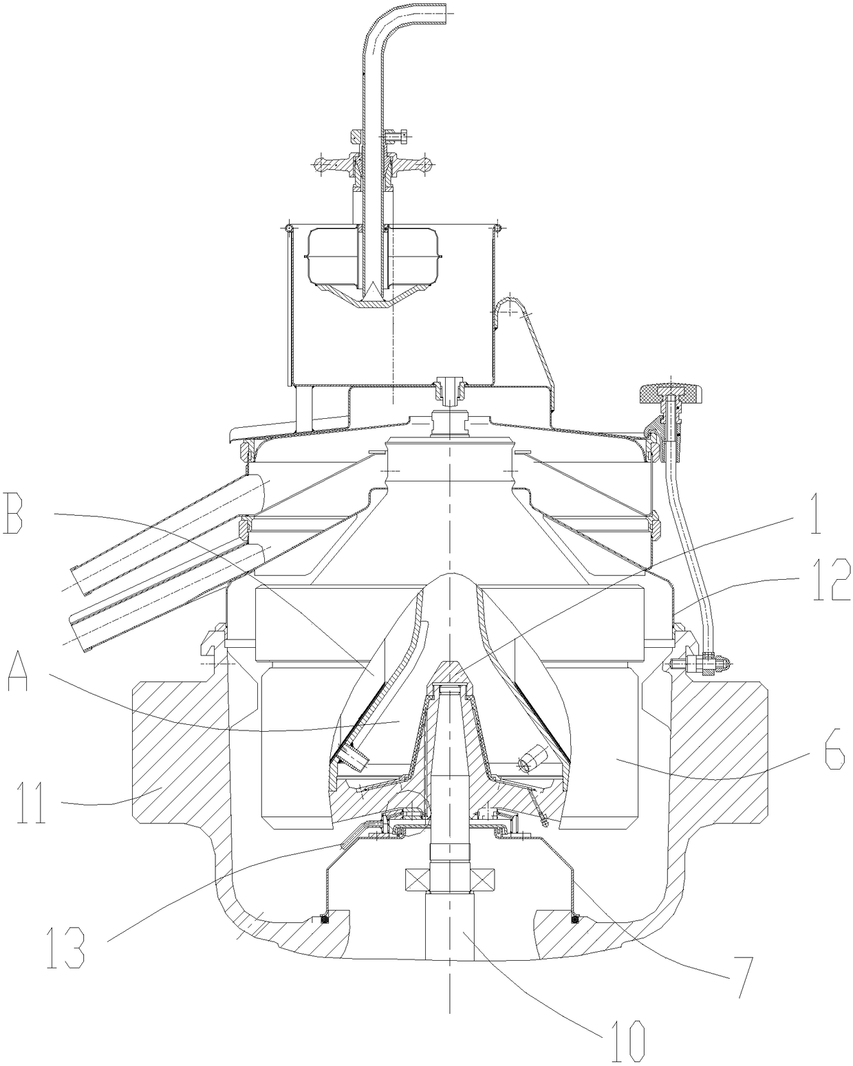
[0025] see figure 1 , the present embodiment is a drum core cooling device for preventing latex concentration and separation process bonding, one end of the vertical shaft 10 is located in the base 11 and connected to the core of the drum 6 in the base 11, and is located in the cavity of the base 11 A bearing 9 is arranged on the vertical shaft 10, and a protective cover assembly is arranged between the bearing 9 and the core of the rotating drum 6.

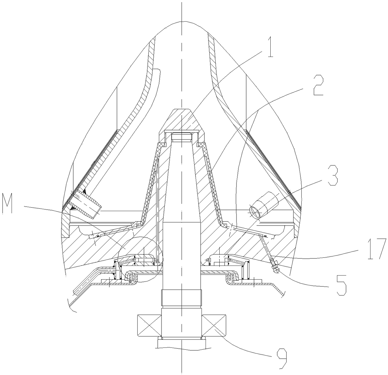
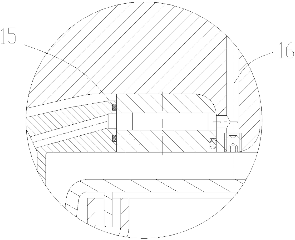
[0026] A core cooling device 2 is arranged on the surface of the core of the drum 6, and a centripetal pump 3 is arranged at the connection between the vertical shaft 10 and the bottom of the core of the drum 6, such as figure 2 shown. Centripetal pump 3 is a cylindrical structure with 8 helical blades, see Figure 4 , there are three screw holes conn...


PUM


Abstract

The invention discloses a cooling device in a rotating drum core part for preventing latex bonding in a concentration and separation process. The rotary drum core cooling device comprises a machine base, a rotating drum positioned in the machine base and a vertical shaft connected with the rotating drum core part; the cooling device is characterized in that a core part cooling device body is arranged on the surface of the rotating drum core part, centripetal pumps are arranged at the joint of the vertical shaft and the rotating drum core part, and the output ports of the centripetal pumps arearranged in the axial direction of the rotating drum and communicate with inner flow channels leading to the core part cooling device body; and the rotating drum core part is further provided with a backflow channel communicating with the core cooling device body, and an atomizing nozzle is arranged at a liquid outlet of the backflow channel. According to the cooling device, centrifugal force is utilized to enable a cooling liquid to enter the rotating drum core part to be cooled through the interior of the rotating drum core part, so that the phenomena of space occupation by additional cooling auxiliary parts and complex structure are reduced; and the rotating drum core part and the bottom part are subjected to sufficient heat exchange, the atomizing nozzle further cools the space betweena protective cover and the rotating drum, so that generation and growth of latex ball caps are avoided, and the latex separation quality is improved.

Description

technical field [0001] The invention relates to separator manufacturing technology, in particular to a drum core cooling device for preventing latex concentration and separation process from sticking. Background technique [0002] Latex separator is mainly used to remove water and a small amount of solid impurities in natural latex to achieve the purpose of concentrating latex. Due to the high viscosity of natural latex, it is difficult to separate, so this series of latex separators are usually manual slag removal and high-speed high-separation factor equipment. Due to the high speed, the bearing will generate a lot of heat, although cooling the bearing can take away part of the heat, such as the patent announcement number CN102278380B which the applicant applied for and obtained the patent right in 2011, a technology for the bearing cooling device of a two-stage pusher centrifuge , the effect is obvious for general material separation, but in the application of latex conc...

Claims


Application Information

Patent Timeline
IPC IPC(8): B04B15/02B04B7/08
CPCB04B7/08B04B15/02
Inventor 吕丽珍陶渊卿
Owner ZHEJIANG QINGJI IND
Learn More