Numerically-controlled lathe allowing cutters to be installed conveniently

A technology for CNC lathes and tools, applied in the field of CNC lathes, can solve the problems of cumbersome, tool surface damage, labor and other problems, and achieve the effects of scientific and reasonable structure, safe and convenient use, and avoidance of inability to move.

Active Publication Date: 2018-06-01
NANTONG XINRUIT MACHINERY CO LTD
View PDF5 Cites 10 Cited by
  • Summary
  • Abstract
  • Description
  • Claims
  • Application Information

AI Technical Summary

Problems solved by technology

[0003] The present invention provides a CNC lathe that is convenient for tool installation, which can effectively solve the problem that the CNC lathe proposed in the above background technology needs to replace different tools when processing different components, but the current method for changing tools is cumbersome and time-consuming. The installed tool is easy to break away from the tool holder, thus throwing out the lathe, posing a threat to the operator; because the CNC lathe cannot adjust the distance between the tool and the component to be processed, it is more laborious when the CNC lathe processes larger components, and It will cause damage to the surface of the tool and shorten the service life of the tool. The CNC lathe is not equipped with shock-absorbing moving components. On the one hand, the CNC lathe cannot reduce the vibration generated during its normal operation, and on the other hand, the CNC lathe cannot move. There are problems such as limitations in the use area of ​​​​the lathe

Method used


Image

  • Numerically-controlled lathe allowing cutters to be installed conveniently
  • Numerically-controlled lathe allowing cutters to be installed conveniently
  • Numerically-controlled lathe allowing cutters to be installed conveniently

Examples


Embodiment

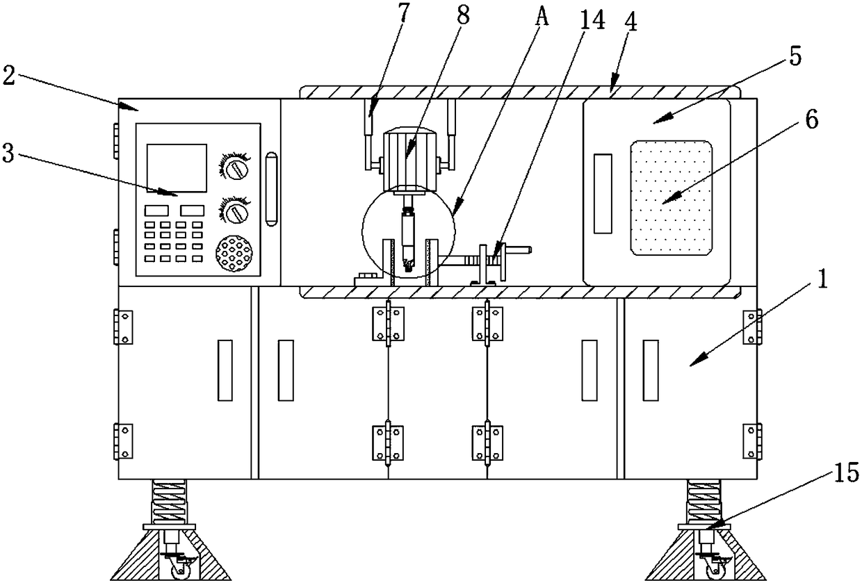
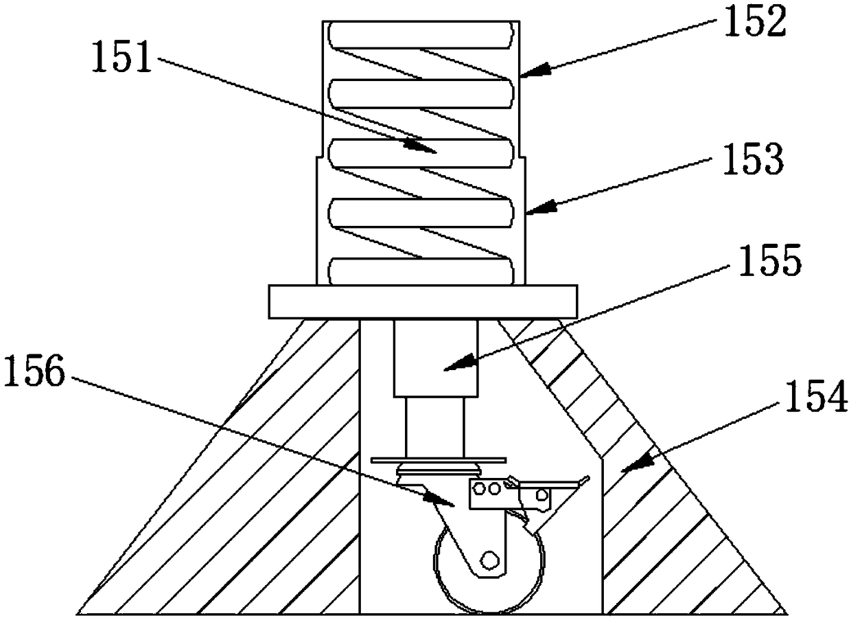
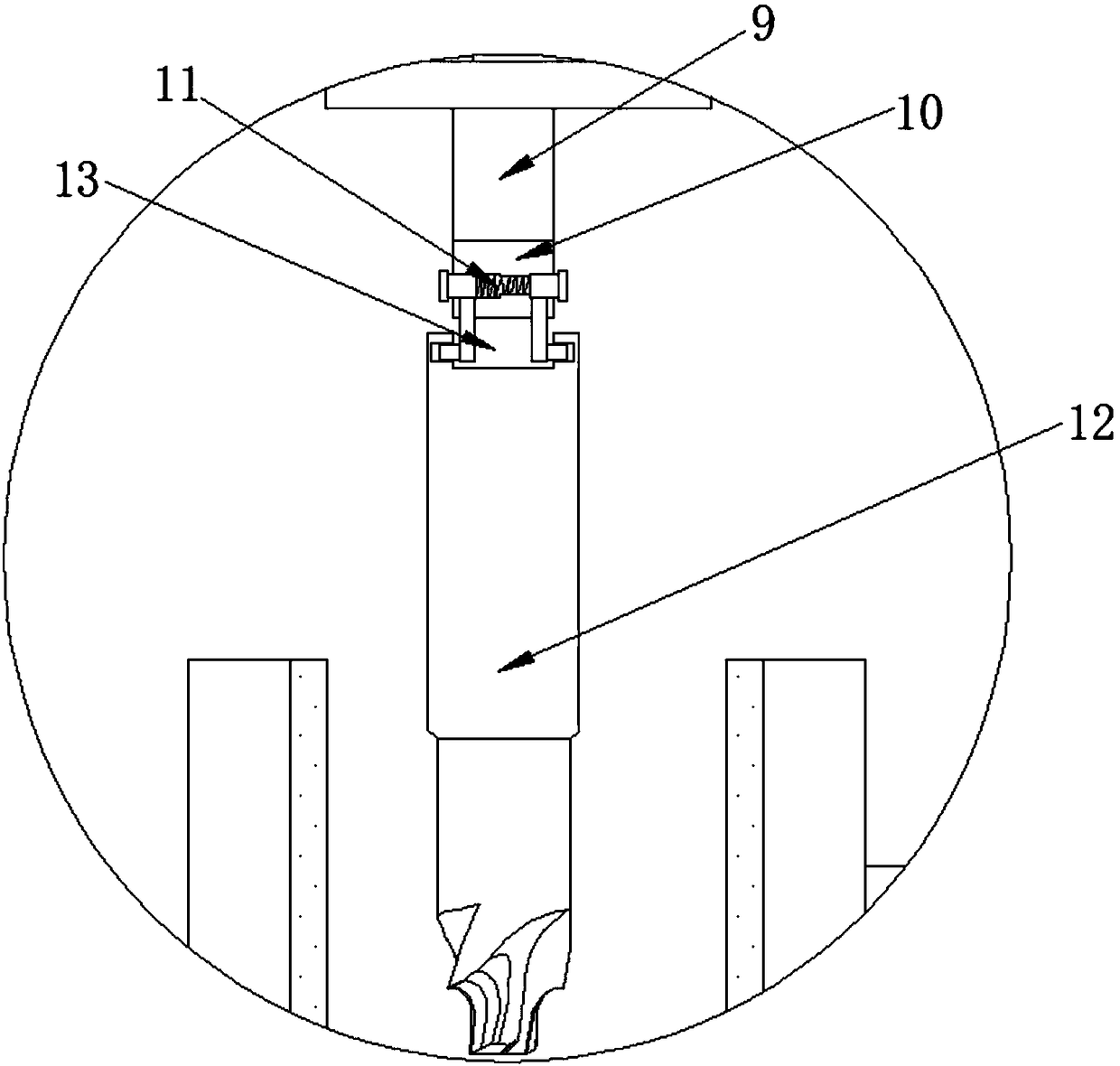
[0022] Example: such as Figure 1-5 As shown, the present invention provides a technical solution, a CNC lathe that is convenient for tool installation, including an operating platform 1, a control box 2, a control panel 3, a slide rail 4, a protective door 5, a window 6, and a first electric telescopic rod 7 , servo motor 8, transmission rod 9, groove 10, mounting assembly 11, cutter 12, card slot 13, fixed assembly 14 and shock-absorbing moving assembly 15, control box 2 is installed on the upper end of one side of operation platform 1, control box 2 A control panel 3 is installed on the outer surface of the rear end, a first electric telescopic rod 7 is installed on the inner side of the upper middle part of the operation platform 1, a servo motor 8 is installed on one side of the lower end of the first electric telescopic rod 7, and a transmission rod 9 is connected to the outer side of the lower end of the servo motor 8 , a groove 10 is provided on the inner side of the b...


PUM


Abstract

The invention discloses a numerically-controlled lathe allowing cutters to be installed conveniently. The numerically-controlled lathe comprises an operation platform, a first electric telescoping rod, a servo motor, an installing assembly, the cutters, a fixed assembly and a damping moving assembly. The first electric telescoping rod is installed on the inner side of the middle portion of the upper end of the operation platform. The servo motor is installed on one side of the lower end of the first electric telescoping rod. The installing assembly is installed in the groove. The cutters are connected below a transmission rod. The fixed assembly is installed on the outer side of the middle portion of the operation platform. The damping moving assembly is installed on the outer side of thelower end of the operation platform. The numerically-controlled lathe is scientific and reasonable in structure and safe and convenient to use, the installing assembly is arranged, the cutters can bereplaced or installed fast, and the problems that when the numerically-controlled lathe machines different components, the different cutters need to be replaced, however, an existing cutter replacingmethod is tedious and wastes time and labor, the installed cutters break away from a cutter rest easily, and an operator is threatened are avoided.

Description

technical field [0001] The invention relates to the field of numerically controlled lathes, in particular to a numerically controlled lathe which facilitates tool installation. Background technique [0002] CNC lathe is the abbreviation of digital control lathe, which is an automatic lathe equipped with a program control system. The control system can logically process the program specified by the control code or other symbolic instructions, decode it, express it in coded numbers, input it into the numerical control device through the information carrier, and send out various control signals from the numerical control device after calculation and processing. Control the movement of the lathe, and automatically process the parts according to the shape and size required by the drawing. The CNC lathe solves the problem of complex, precise, small batch and multi-variety parts processing. It is a flexible and high-efficiency machine tool. Automated lathes represent the developme...

Claims


Application Information

Patent Timeline
Patent Type & Authority Applications(China)
IPC IPC(8): B23Q3/00B23Q3/12B23Q11/08B23Q15/22B23Q1/01
CPCB23Q1/01B23Q3/00B23Q3/12B23Q11/08B23Q15/22
Inventor 不公告发明人
Owner NANTONG XINRUIT MACHINERY CO LTD
Why Eureka
Try Eureka