
PC beam bearing machining clamping device and clamping method

A clamping device and support technology, applied in positioning devices, metal processing equipment, metal processing machinery parts, etc., can solve the problems of high labor intensity of operators, poor workpiece processing size, loose pressure plate, etc., to improve processing accuracy and The effect of production efficiency, convenient clamping and simple structure design

Pending Publication Date: 2018-06-01
CHINA RAILWAY BAOJI BRIDGE GRP
View PDF0 Cites 0 Cited by
  • Summary
  • Abstract
  • Description
  • Claims
  • Application Information

AI Technical Summary

Problems solved by technology

At present, the workpiece is aligned manually, aligned, and then the bolts are pressed against the pressure plate to compress the workpiece. This method is not only inefficient but also labor-intensive for the operator. In addition, there are vibrations caused by the large amount of cutting during processing, which may cause the pressure plate The phenomenon of looseness causes the workpiece processing size to be out of tolerance

Method used


Image

  • PC beam bearing machining clamping device and clamping method
  • PC beam bearing machining clamping device and clamping method
  • PC beam bearing machining clamping device and clamping method

Examples


Embodiment Construction

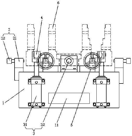
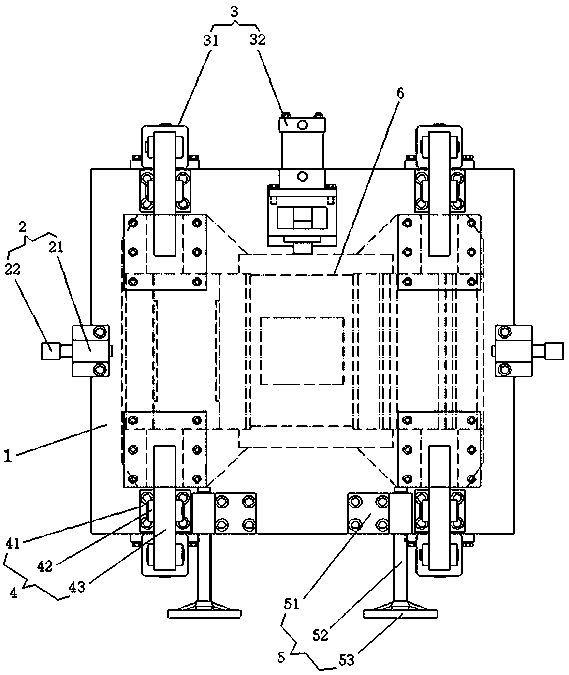
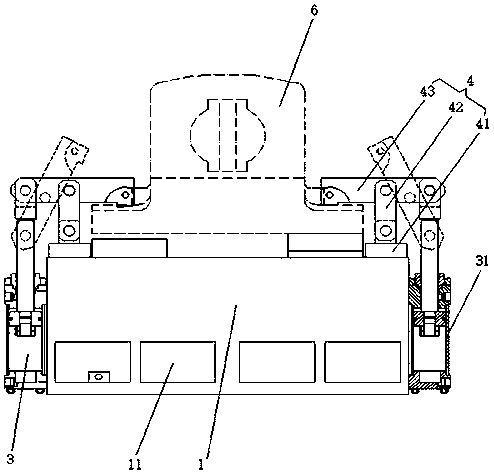
[0018] Such as Figures 1 to 3 As shown, the PC beam support processing and clamping device of the present invention includes a worktable 1, a centering mechanism 2, a hydraulic cylinder 3, a connecting rod mechanism 4 and a fine-tuning mechanism 5.

[0019] The workbench 1 has a square structure, and an installation groove 11 is provided on the side walls around its lower end.

[0020] The centering mechanism 2 is a pair symmetrically installed on the left and right sides of the upper end of the workbench 1. Each centering mechanism 2 includes a centering support 21 and a centering adjustment screw 22; the centering support 21 is fixed on the The middle part of the left and right side walls of the upper end of the workbench 1, its top stretches out to the top of the table top of the workbench 1 and the centering adjustment screw rod 22 is horizontally installed on the stretched end.

[0021] The hydraulic cylinders 3 are symmetrically arranged on the front and rear sides of ...


PUM


Abstract

The invention relates to a PC beam support machining clamping device and a clamping method. The PC beam bearing machining clamping device includes a worktable and a middle mechanism arranged on the workable, a hydraulic oil cylinder, a connecting rod mechanism and a fine tuning mechanism; the middle mechanism is symmetrically installed on the middle portion of the left side and the middle portionof the right side of the upper end of the worktable and is connected with the PC beam support placed on the worktable; the hydraulic oil cylinder is connected with the external hydraulic system. The hydraulic oil cylinder comprises a longitudinal hydraulic oil cylinder symmetrically arranged on the front and back sides of the worktable and a transverse hydraulic oil cylinder mounted on the top surface of the worktable. The connecting rod mechanism is symmetrically installed on the front and back top surface of the worktable, one end of the connecting rod mechanism is connected withthe piston rod of the longitudinal hydraulic oil cylinder, and the other end of the connecting rod mechanism connects with the PC beam support placed on the worktable, and the fine tuning mechanism is installed at the front side of the upper surface of the worktable and connected with the PC beam support placed on the worktable. The PC beam bearing machining clamping device and the clamping method have simpleand reasonable structure design, convenient installation and high efficiency, and can improve the processing precision and production efficiency of the PC beam support.

Description

technical field [0001] The invention relates to a clamping device, in particular to a PC beam support processing clamping device and a clamping method. Background technique [0002] In urban rail transit projects, PC beam supports are the basic unit of lines. Large and inefficient, this clamping method can not only reduce the labor intensity of the operator, but also improve labor efficiency. The processing of PC beam bearings not only has a large batch size, but also requires high processing accuracy, shape and position tolerances and surface quality. How to control the shape and position tolerances and surface quality requirements is the difficulty and key to its processing. At present, the workpiece is aligned manually, aligned, and then the bolts are pressed against the pressure plate to compress the workpiece. This method is not only inefficient but also labor-intensive for the operator. In addition, there are vibrations caused by the large amount of cutting during pro...

Claims


Application Information

Patent Timeline
Patent Type & Authority Applications(China)
IPC IPC(8): B23Q3/08
CPCB23Q3/082
Inventor 郭江海冯来义吉敏廷严安宁张向祎冯志刘一涛
Owner CHINA RAILWAY BAOJI BRIDGE GRP
Learn More