Gearbox oil pump shell
A technology for oil pump casings and gearboxes, which is applied to pump components, rotary piston type/oscillating piston type pump components, transmission parts, etc., which can solve problems such as poor sealing effect, reduce oil leakage, and increase thickness , the effect of increasing the contact area
- Summary
- Abstract
- Description
- Claims
- Application Information
AI Technical Summary
Problems solved by technology
Method used
Image
Examples
Embodiment 1
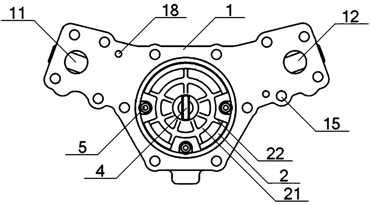
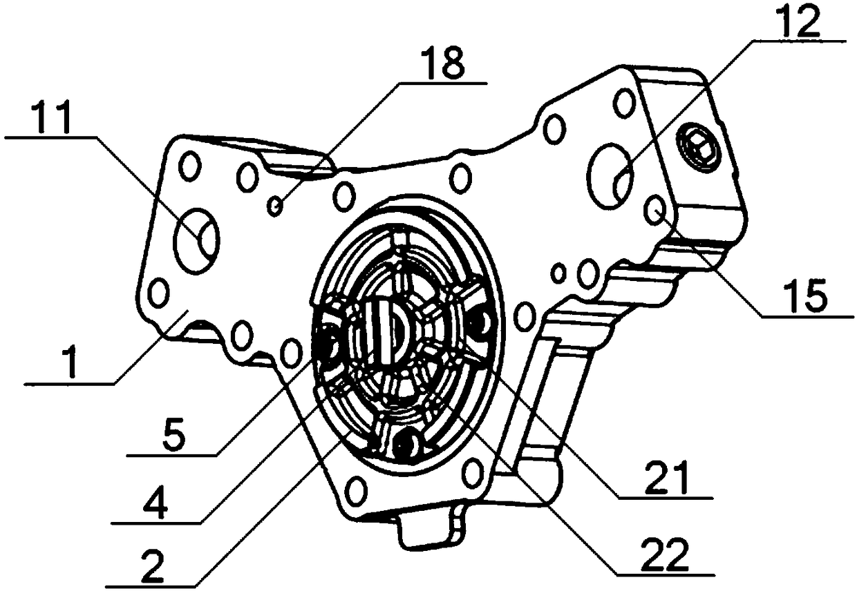
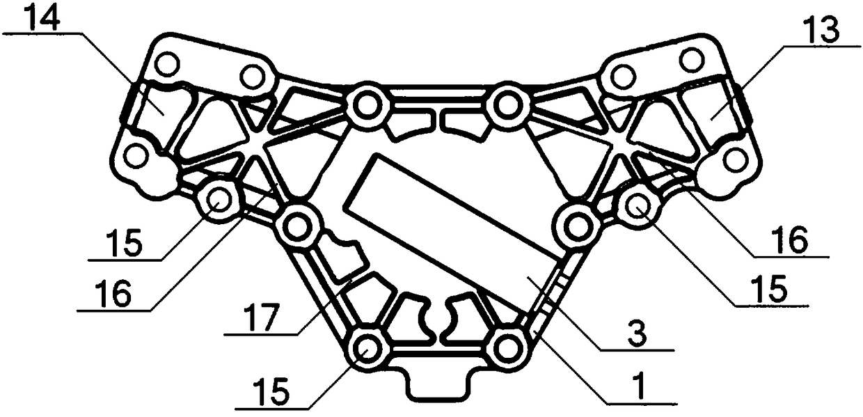
[0040] see Figure 1 to Figure 5 , a gearbox oil pump housing, including a housing body 1 and a cover plate 2, the middle part of one end surface of the housing body 1 is connected with the cover plate 2 through bolts 5, and the upper left part of one end surface of the housing body 1 An oil inlet 11 is provided, an oil outlet 12 is provided on the upper right part of one end surface of the housing body 1, and an oil inlet passage 13 communicating with the oil inlet 11 is provided on the upper left part of the other end surface of the housing body 1 The upper right part of the other end surface of the housing body 1 is provided with an oil outlet 14 communicating with the oil outlet 12; the end surface of the housing body 1 where the cover plate 2 is installed is provided with two positioning pin holes 18; A safety valve 3 is provided in the middle of the end surface of the housing body 1 away from the cover plate 2; the transmission oil pump housing is made of aluminum alloy....
Embodiment 2
[0042] Basic content is the same as embodiment 1, the difference is:
[0043] see Figure 1 to Figure 4, the periphery of the housing body 1 is provided with a plurality of bolt holes 15, the housing body 1 is fixed on the gearbox housing through the bolt holes 15, and the depth of the bolt holes 15 is equal to the thickness of the housing body 1; The end surface of the housing body 1 away from the cover plate 2 is provided with a plurality of No. 1 reinforcing ribs 16, and the No. 1 reinforcing ribs 16 are arranged crosswise on the connection line of the bolt holes 15; the housing body 1 is far away from the cover plate 2 A plurality of No. 2 reinforcing ribs 17 are provided on the end face of the housing, and the No. 2 reinforcing ribs 17 are located between the bolt holes 15 and the housing body 1; the housing body 1 has a Y-shaped structure.
Embodiment 3
[0045] Basic content is the same as embodiment 1, the difference is:
[0046] see Figure 1 to Figure 4 , the outer end surface of the cover plate 2 is provided with a third reinforcing rib 21 and a plurality of fourth reinforcing ribs 22, the third reinforcing rib 21 is a ring structure, the third reinforcing rib 21 is concentric with the cover plate 2, and the fourth reinforcing rib The No. 4 reinforcing rib 22 is arranged on the connecting line between the center of the cover plate 2 and the outer periphery of the cover plate 2, and the No. 4 reinforcing rib 22 intersects with the No. 3 reinforcing rib 21; For the rotor 6 and the outer rotor 7 , the middle part of the cover plate 2 is equipped with a limiting flat 4 , and the shaft portion of the limiting flat 4 is in interference fit with the inner hole of the inner rotor 6 .
PUM
 Abstract
Description
Claims
Application Information
 - R&D
- Intellectual Property
- Life Sciences
- Materials
- Tech Scout
- Unparalleled Data Quality
- Higher Quality Content
- 60% Fewer Hallucinations
Browse by: Latest US Patents, China's latest patents, Technical Efficacy Thesaurus, Application Domain, Technology Topic, Popular Technical Reports.
© 2025 PatSnap. All rights reserved.Legal|Privacy policy|Modern Slavery Act Transparency Statement|Sitemap|About US| Contact US: help@patsnap.com


