
Constant-temperature and constant-humidity air treatment equipment provided with two stages of heat recovery devices

A heat recovery device and air treatment technology, used in lighting and heating equipment, shielding with air flow, energy recovery systems for ventilation and heating, etc.

Pending Publication Date: 2018-06-01
廊坊康平空调制造有限公司
View PDF5 Cites 7 Cited by
  • Summary
  • Abstract
  • Description
  • Claims
  • Application Information

AI Technical Summary

Problems solved by technology

[0003] Taking the constant temperature and humidity air treatment of fresh fans as an example, the difficulty lies in the high temperature and high humidity conditions of the fresh air inlet in summer, because the heating and humidification in winter can be independently controlled by the heating coil and the humidification section, while the cooling and dehumidification in summer are controlled by The cold coil inlet treatment is usually to meet the dehumidification requirements, that is, the moisture content of the air at the outlet of the cold coil meets the design requirements, and the outlet temperature of the cold coil is already lower than the air supply temperature required by the system, so it is necessary to use The heating coil is reheated in order to achieve precise temperature and humidity control; but problems arise: first, in order to cool and dehumidify the imported high-temperature and high-humidity air, the cooling coil needs to consume huge energy; Heating the overcooled air after dehumidification by the cold coil requires additional reheating energy; for:

Method used


Image

  • Constant-temperature and constant-humidity air treatment equipment provided with two stages of heat recovery devices

Examples


Embodiment Construction

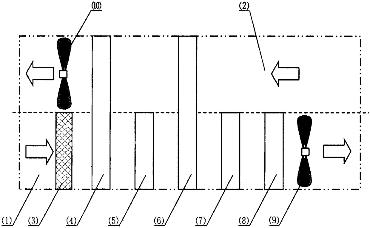
[0019] refer to figure 1 Describe the constant temperature and humidity air treatment equipment of the present invention, taking summer working conditions as an example:

[0020] The fresh air enters the fresh air air conditioning box (1) through the air inlet, and after the fresh air passes through the dust removal and filtering equipment (3) selected by the system, at this time, the fresh air enters the full-heated air-air heat exchanger (4) in a state of high temperature and high humidity, and The low-temperature and low-humidity exhaust air on the other side of the full-hot air-air heat exchanger (4) conducts heat and humidity transfer, thereby greatly reducing the temperature and humidity of the fresh air, and then enters the refrigeration coil (5) for deep cooling, Dehumidification until the moisture content of the outlet state reaches the moisture content of the air supply state point; in this state, the normal state is: although the humidity meets the air supply requi...


PUM


Abstract

The invention relates to constant-temperature and constant-humidity air treatment equipment. The constant-temperature constant-humidity air treatment equipment has the function of conventional constant-temperature and constant-humidity air treatment equipment and is provided with two stages of heat recovery devices, and the stage of heat recovery device close to a fresh air inlet is a full heat recovery air-air heat exchanger. The constant-temperature constant-humidity air treatment equipment has the advantages of excellent energy-saving performance and the flexible control means; compared with a traditional system without a heat recovery device, the full heat recovery air-air heat exchanger of the system can effectively reduce the temperature and humidity of fresh air under a summer working condition, and energy consumption required by a cold coil is greatly reduced; and compared with a system only adopting one stage of full heat recovery air-air heat exchanger, the system is providedwith the second stage of heat exchanger, namely the sensible heat recovery air-air heat exchanger, heat in exhausted air is recovered, energy consumption for reheating the coil is reduced, the freshair reduces the temperature of the exhausted air through the cold amount brought by transition cooling of the cold coil after dehumidification, and the cooling and dehumidification capacity of the fresh air at an inlet is further improved.

Description

technical field [0001] The invention belongs to the category of air conditioning and heat exchange, and relates to a constant temperature and humidity air treatment device with a double-stage heat recovery device. Background technique [0002] The fresh air fan is an effective air purification device that can circulate the indoor air. On the one hand, the indoor dirty air is discharged outside, and on the other hand, the fresh outdoor air is treated (such as purification, heating / cooling, humidification / dehumidification) After that, it is input into the room to ensure that the air entering the room is clean and healthy; common civilian fresh air fans usually only use temperature as the main control reference point, and give a large fluctuation range to the humidity in the controlled area; but for some special processes Permanent air conditioning, which is beneficial to some places in precision printing, tobacco, biopharmaceutical, electronic chip manufacturing, precision mac...

Claims


Application Information

Patent Timeline
Patent Type & Authority Applications(China)
IPC IPC(8): F24F7/007F24F3/14F24F5/00F24F12/00F24F13/30
CPCF24F3/14F24F5/0007F24F7/007F24F12/006F24F13/30
Inventor 张文丰
Owner 廊坊康平空调制造有限公司
Learn More