Eureka AIR delivers breakthrough ideas for toughest innovation challenges, trusted by R&D personnel around the world.

Vapor-liquid phase flow heat transfer module

A vapor-liquid and liquid technology, applied in the field of vapor-liquid phase flow heat transfer module, can solve the problems of long heat transfer path of the pipe body, inability of the working medium to return quickly, poor heat transfer efficiency, etc.

Active Publication Date: 2018-06-01
ASIA VITAL COMPONENTS SHENZHEN CO LTD
View PDF5 Cites 1 Cited by
  • Summary
  • Abstract
  • Description
  • Claims
  • Application Information

AI Technical Summary

Problems solved by technology

[0004] However, the radiator of the current vapor-liquid phase flow heat transfer technology is cooled by a fan, and the fan cooling requires a large heat exchange area and must occupy a large space in the system. The heat path is also long, and the working medium in the tube body cannot return quickly, resulting in poor heat exchange efficiency

Method used


Image

  • Vapor-liquid phase flow heat transfer module
  • Vapor-liquid phase flow heat transfer module
  • Vapor-liquid phase flow heat transfer module

Examples


Embodiment Construction

[0038] The above-mentioned purpose of the present invention and its structural and functional characteristics will be described according to the preferred embodiments of the accompanying drawings.

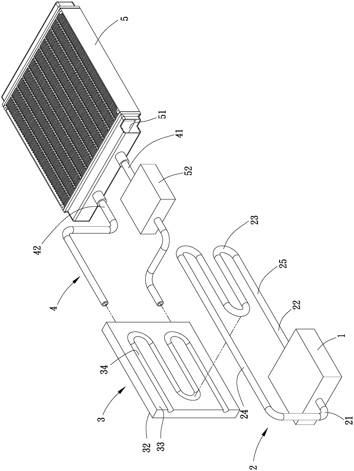
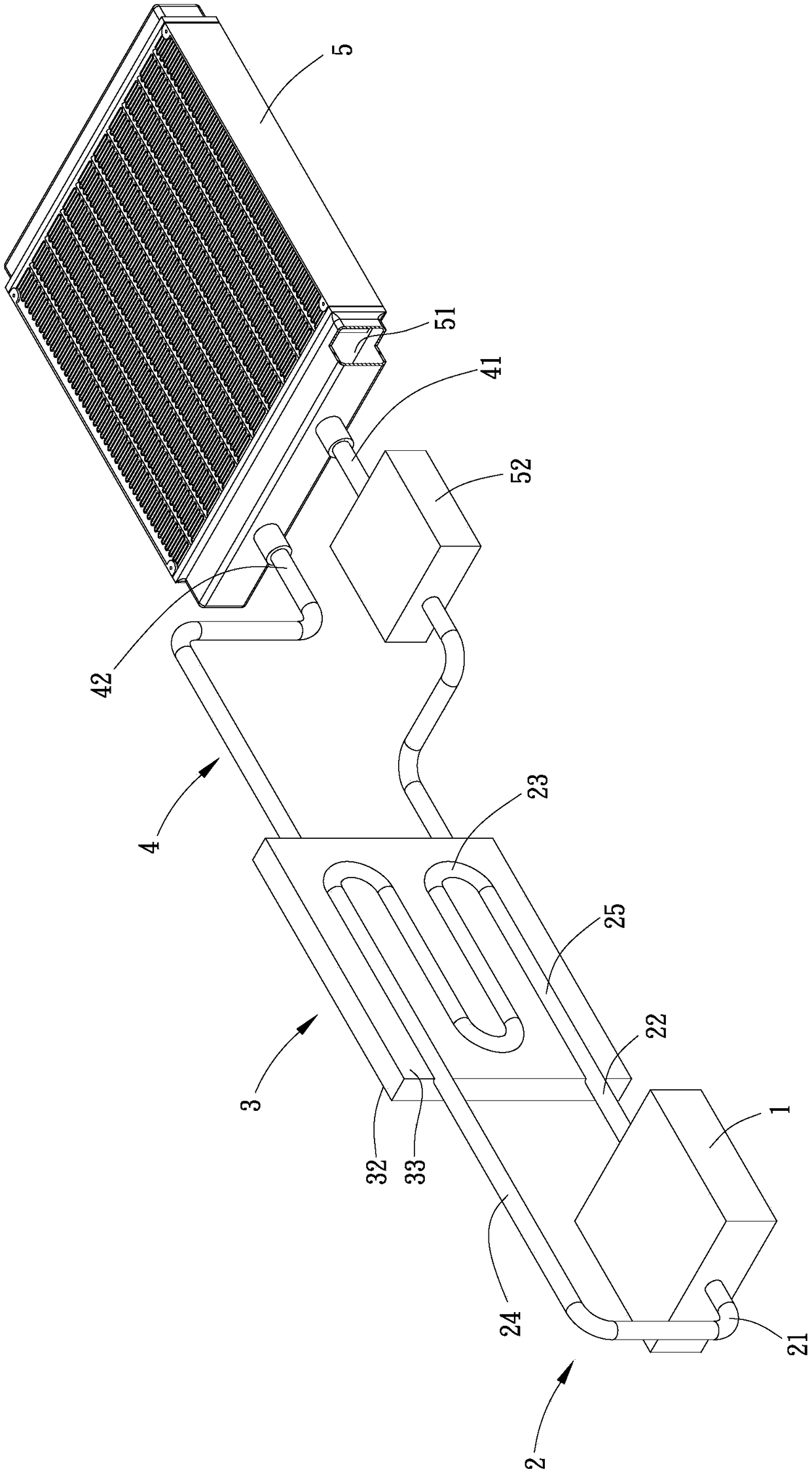
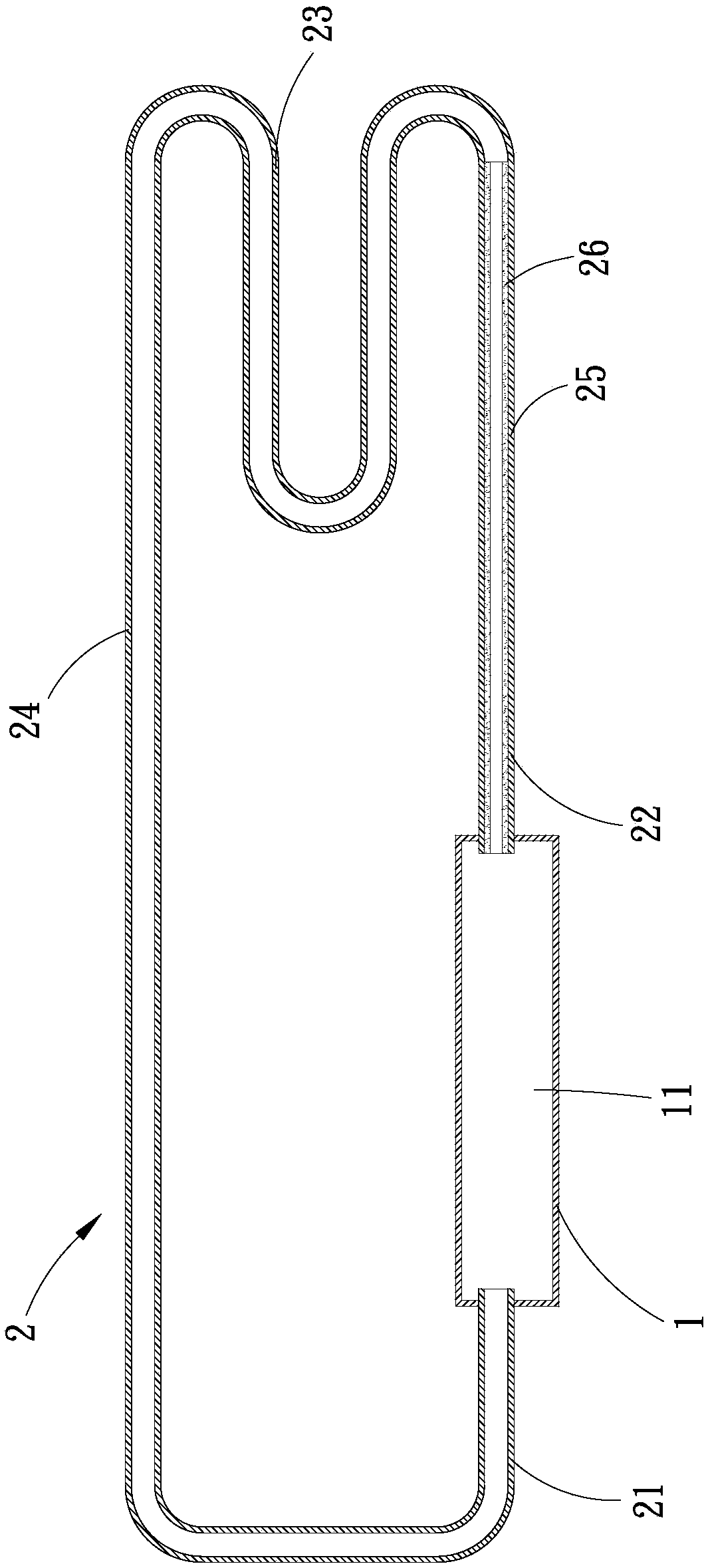
[0039] Please refer to Figure 1A , Figure 1B , Figure 1C and Figure 1D , is the perspective exploded view and stereo combination view of the first embodiment of the vapor-liquid phase flow heat transfer module of the present invention, the sectional view of the evaporator and the evaporator tube, and the sectional view of the heat exchanger and the radiator tube. As shown in the figure, this The vapor-liquid phase flow heat transfer module of the invention comprises at least one evaporator, at least one evaporator tube, at least one heat exchanger, at least one radiator tube and at least one radiator. In this embodiment, it is represented as an evaporator 1, an evaporator tube body 2, a heat exchanger 3, a radiator tube body 4 and a radiator 5, but it is not limited thereto, ...


PUM


Abstract

The invention provides a vapor-liquid phase flow heat transfer module. The vapor-liquid phase flow heat transfer module comprises at least one evaporator, at least one evaporator pipe, at least one heat exchanger and at least one radiator pipe, wherein each evaporator is internally provided with a first cavity filled with a first working medium; each evaporator pipe is provided with a first end, asecond end and a condensation section located between the first end and the second end, and the first end and the second end communicate with the first cavity of the corresponding evaporator to forma loop of the first working medium; each heat exchanger is internally provided with a heat exchange cavity and further provided with a first side face and a second side face which are used for attachment of the condensation section of the corresponding evaporator pipe; and each radiator pipe communicates with the heat exchange cavity of the corresponding heat exchanger and at least one radiator, and allows a second working medium to flow to form a loop of the second working medium.

Description

technical field [0001] The invention relates to the field of heat dissipation, in particular to a vapor-liquid phase flow heat transfer module capable of reducing the heat transfer area and shortening the heat transfer path and increasing the heat transfer efficiency. Background technique [0002] The commonly used heat dissipation technologies are fans and heat dissipation fins. However, as the efficiency of current electronic equipment increases, the electronic components used for signal processing and calculation also generate higher heat than the previous electronic components. Vapor-liquid phase flow heat transfer technology has begun to be applied to heat dissipation of high heat flux products or environments. Since the theoretical heat flux of phase change can reach more than 50W / cm2 and does not require additional power, the vapor-liquid phase flow heat transfer technology has Features of heat transfer and energy saving. [0003] The current vapor-liquid phase flow ...

Claims


Application Information

Patent Timeline
Patent Type & Authority Applications(China)
IPC IPC(8): F28D15/02F28D15/04
CPCF28D15/0266F28D15/0275F28D15/04
Inventor 高百龄陈旦军李国辉
Owner ASIA VITAL COMPONENTS SHENZHEN CO LTD
Why Eureka
Eureka Blog
Learn More