An auxiliary fiber arrangement device for optical fiber surround system

An optical fiber and winding technology, which is applied in the field of optical fiber winding auxiliary fiber arrangement device, can solve the problems of poor uniformity of pressure distribution, low efficiency, and low degree of winding automation

Inactive Publication Date: 2021-07-06
CHONGQING HUAYU ELECTRIC GRP
View PDF10 Cites 0 Cited by
  • Summary
  • Abstract
  • Description
  • Claims
  • Application Information

AI Technical Summary

Problems solved by technology

[0004] In view of the above-mentioned deficiencies existing in the prior art, the purpose of the present invention is to solve the problems of poor uniformity of pressure distribution in the existing optical fiber winding process, resulting in poor symmetry of the optical fiber ring, low degree of winding automation and low efficiency, and provides a The auxiliary fiber arrangement device for optical fiber winding can realize the uniform pressure on the optical fiber during the winding process in the optical fiber ring, thereby improving the symmetry of the optical fiber ring, and the automatic degree of fiber arrangement is higher, thereby improving the efficiency of optical fiber winding

Method used


Image

  • An auxiliary fiber arrangement device for optical fiber surround system

Examples


Embodiment

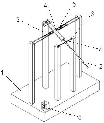
[0022] Example: see figure 1 , an optical fiber surround system auxiliary fiber arrangement device, including a frame 1, a fiber arrangement rod 2 and a counterweight 4. One end of the fiber rod 2 is rotatably connected to the frame 1, and the other end is a T-shaped compression head; wherein, the frame 1 has a row of fiber rod pillars 3, and the fiber rod 2 and the The pillar 3 is rotatably connected. The counterweight 4 is an iron block and is installed on the fiber rod 2 , and the counterweight 4 is close to the end of the fiber rod 2 connected to the pillar 3 .

[0023] There are two electromagnets 5 symmetrically distributed on the left and right sides of the counterweight 4: electromagnet Ⅰ and electromagnet Ⅱ, and the two electromagnets 5 are located on the same horizontal plane; among them, the electromagnet Ⅰ is located on the left side of the fiber rod 2, and the electromagnet Ⅱ It is located on the right side of fiber rod 2. There are two tension sensors 6 symmet...


PUM


Abstract

The invention discloses an auxiliary fiber-discharging device made around an optical fiber, which includes a frame and a fiber-discharging rod; the counterweight is iron, and two electromagnets are symmetrically distributed on the left and right sides of the counterweight, and There are two tension sensors symmetrically distributed on the left and right sides of the machine, and the two tension sensors are respectively connected to the fiber rod through a tension spring; there is a controller on the frame, and the two tension sensors are connected to the controller. After changing the switch, it is connected with two electromagnets, wherein, the left electromagnet, the right tension sensor and the controller form a closed-loop control loop, and the right electromagnet, the left tension sensor and the controller form another closed-loop control loop. The invention can realize the uniform pressure on the optical fiber during the winding process of the optical fiber ring, thereby improving the symmetry of the optical fiber ring, and the automatic degree of optical fiber arrangement is higher, thereby improving the efficiency of optical fiber winding.

Description

technical field [0001] The invention relates to the technical field of optical fiber gyroscopes, in particular to an auxiliary fiber-discharging device for optical fiber wrapping. Background technique [0002] The fiber optic gyroscope is an inertial instrument sensitive to the angular rate of rotation using the Sagnac effect. It is an important member of the inertial navigation field. It has been widely used in aerospace, national defense and military industries, and has gradually been applied in civilian fields such as navigation, surveying and mapping, and oil exploration. The fiber optic gyroscope is composed of a light source, an optical coupler, a Y-waveguide integrated optical device, a PIN detector and a fiber optic ring, among which the fiber optic ring is a device that produces the Sagnac effect. In order to achieve high sensitivity accuracy, the fiber ring needs to have good optical reciprocity, stress distribution symmetry and temperature insensitivity. Arrange...

Claims


Application Information

Patent Timeline
IPC IPC(8): G01C25/00G01C19/72
CPCG01C19/72G01C25/00
Inventor 陈来柱杨小均
Owner CHONGQING HUAYU ELECTRIC GRP
Why Eureka
Try Eureka