
Method for adjusting inclination angle of light beams and illumination device for adjusting inclination angle of light beams

A technology of beam inclination and lighting device, which is used in measurement devices, optical testing of flaws/defects, material analysis by optical means, etc. performance, simplicity of operation, and improved consistency

Inactive Publication Date: 2018-06-01
SHANGHAI MICRO ELECTRONICS EQUIP (GRP) CO LTD
View PDF6 Cites 2 Cited by
  • Summary
  • Abstract
  • Description
  • Claims
  • Application Information

AI Technical Summary

Problems solved by technology

[0011] The invention provides a method for adjusting the inclination angle of the light beam, which is used to solve the requirement that the LED annular dark field illumination device and the optical fiber annular dark field illumination device can only form a certain illumination field of view, and cannot meet the requirements of monopolar illumination. The problem of the uniformity of the irradiation light angle and the uniformity of the illumination

Method used


Image

  • Method for adjusting inclination angle of light beams and illumination device for adjusting inclination angle of light beams
  • Method for adjusting inclination angle of light beams and illumination device for adjusting inclination angle of light beams
  • Method for adjusting inclination angle of light beams and illumination device for adjusting inclination angle of light beams

Examples


Embodiment 1

[0046] A method for adjusting the inclination angle of a light beam, comprising the steps of:

[0047] Step 1: Use a collimating lens to collimate the beam, and the collimated beam has a small divergence angle of the light in the beam;

[0048] Step 2: Using an angle adjuster to adjust the inclination angle of the collimated light beam by means of reflection adjustment or refraction adjustment.

Embodiment 2

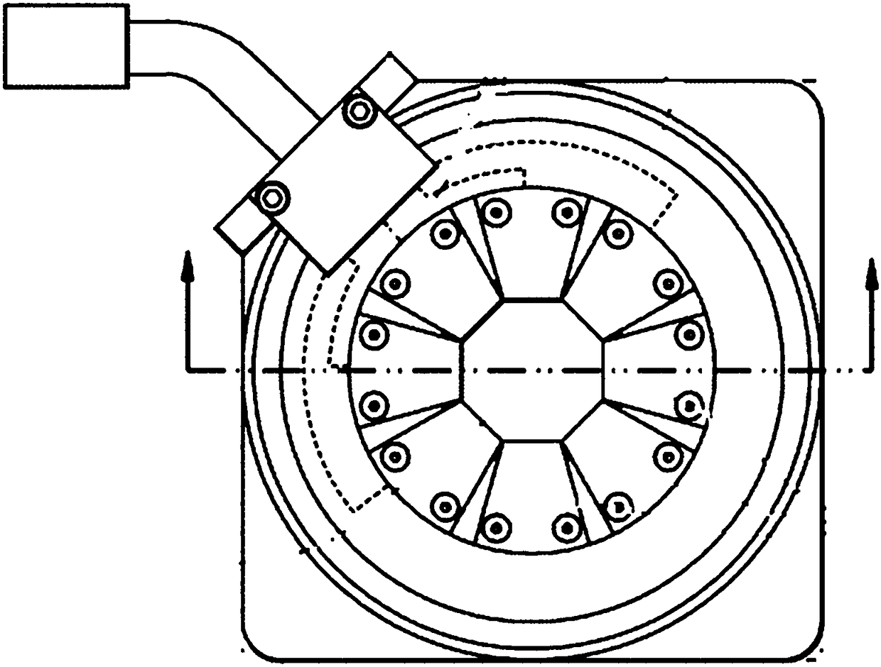
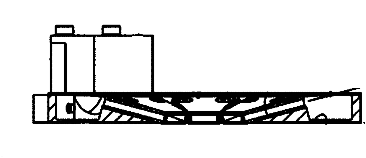
[0050] See Figure 12 , a lighting device for adjusting the inclination angle of light beams, including four sets of lighting mechanisms, the lighting mechanisms include a light source 1, a collimating lens 2 and an angle adjuster arranged along the direction of light propagation, the light source 1 emits light beams that pass through the collimator The straight lens 2 is adjusted to become a parallel light beam, and then the light beam is adjusted by the angle adjuster to realize the angle deflection of the light beam, and is incident on the surface of the flat plate 5 to be tested, thereby realizing a large-angle oblique incident lighting effect.

[0051] The angle adjuster includes a wedge prism 3 and a rotation adjustment mechanism 4 for controlling the rotation of the wedge prism 3 along its axis, the wedge prism 3 is located on the rear focal plane of the collimator lens 2, and the rotation adjustment mechanism 4. Control the rotation of the wedge prism 3 along its axis ...

Embodiment 3

[0068] See Figure 19 The difference between the third embodiment and the second embodiment is that the angle adjuster is a micromirror array 6, and the light beam emitted by the light source 1 passes through the collimating lens 2, and the light beam becomes parallel light, and the divergence angle of the light in the light beam is very large. Small, the angular deflection of the light beam is realized by the micro-mirror array 6, and it is incident on the surface of the plate 5 to be tested, so as to achieve a large-angle oblique incident lighting effect, and the angular deviation range of the light in the light beam is <1 degree. By adjusting the micro-mirror array 6, the angle adjustment of the light beam incident on the surface of the flat plate 5 to be measured is realized.


PUM

PropertyMeasurementUnit
Heightaaaaaaaaaa
Divergence angleaaaaaaaaaa

Abstract

The invention discloses a method for adjusting the inclination angle of light beams. The method comprises steps as follows: S1, the light beams are collimated by a collimating lens, and the divergenceangle of light rays in the collimated light beams is smaller; S2, the inclination angle of the collimated light beams is adjusted by an angle regulator. The angle consistency of the light beams is improved, the uniformity of the illumination field of view is improved, the operation is simple and the production efficiency is improved. The invention also discloses an illumination device for adjusting the inclination angle of the light beams. The illumination device comprises at least one illumination mechanism, wherein the illumination mechanism comprises a light source, the collimating lens and the angle regulator which are arranged in the light ray propagation direction, light beams emitted by the light source are adjusted by the collimating lens to become parallel light beams, then, thelight beams are adjusted by the angle adjuster, angle deflection of the light beams is realized, the light beams are irradiated to the surface of a to-be-detected panel, and the large-angle oblique incidence illumination effect is realized.

Description

technical field [0001] The invention relates to the field of machine vision, in particular to a method for adjusting the inclination angle of a light beam and an illumination device for adjusting the inclination angle of the light beam. Background technique [0002] In the field of machine vision, ring-shaped dark-field lighting is widely used. The ring-shaped dark-field lighting device provides uniform lighting for detecting defect features such as surface depressions, protrusions, and scratches on the surface to be tested. The uniformity of lighting is related to Defect detection quality. [0003] At present, the commonly used ring-shaped dark-field lighting devices include light-emitting diode (LED) ring-shaped dark-field lighting devices and fiber-optic ring-shaped dark-field lighting devices. In recent years, with the development of the semiconductor industry and the replacement of computers, electronic products, detectors and other products, people have higher and hig...

Claims


Application Information

Patent Timeline
IPC IPC(8): G01N21/88
CPCG01N21/8806G01N2021/8835G01N2201/0631
Inventor 王赛申永强
Owner SHANGHAI MICRO ELECTRONICS EQUIP (GRP) CO LTD
Features
  • Generate Ideas
  • Intellectual Property
  • Life Sciences
  • Materials
  • Tech Scout
  • Unparalleled Data Quality
  • Higher Quality Content
  • 60% Fewer Hallucinations
Learn More