A method for hydraulically forming a container roof
A hydraulic forming and container technology, applied in forming tools, stamping machines, presses, etc., can solve the problems of high procurement costs and reduce equipment procurement costs, and achieve good synchronization, reduce equipment procurement costs, flow and uniform effects
- Summary
- Abstract
- Description
- Claims
- Application Information
AI Technical Summary
Problems solved by technology
Method used
Image

Examples
Embodiment 1
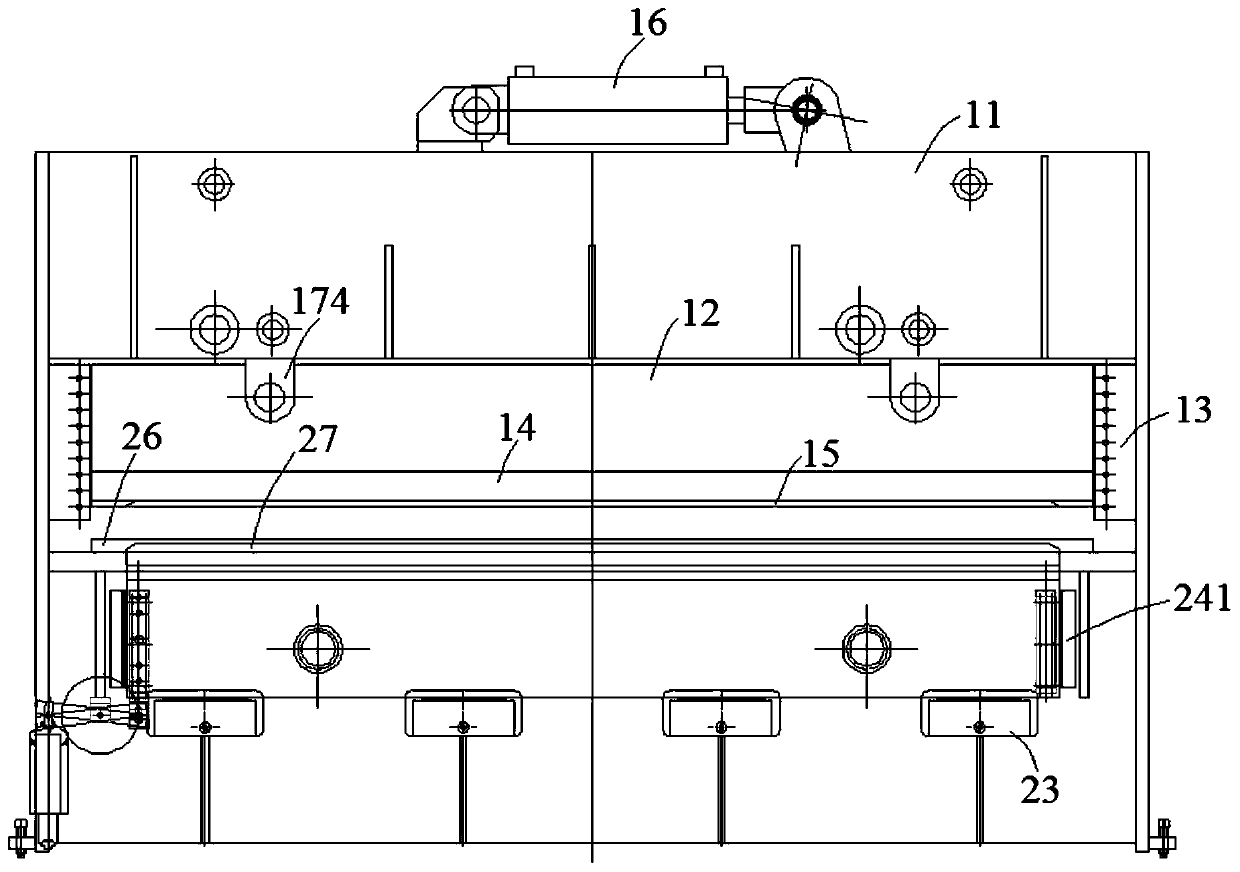
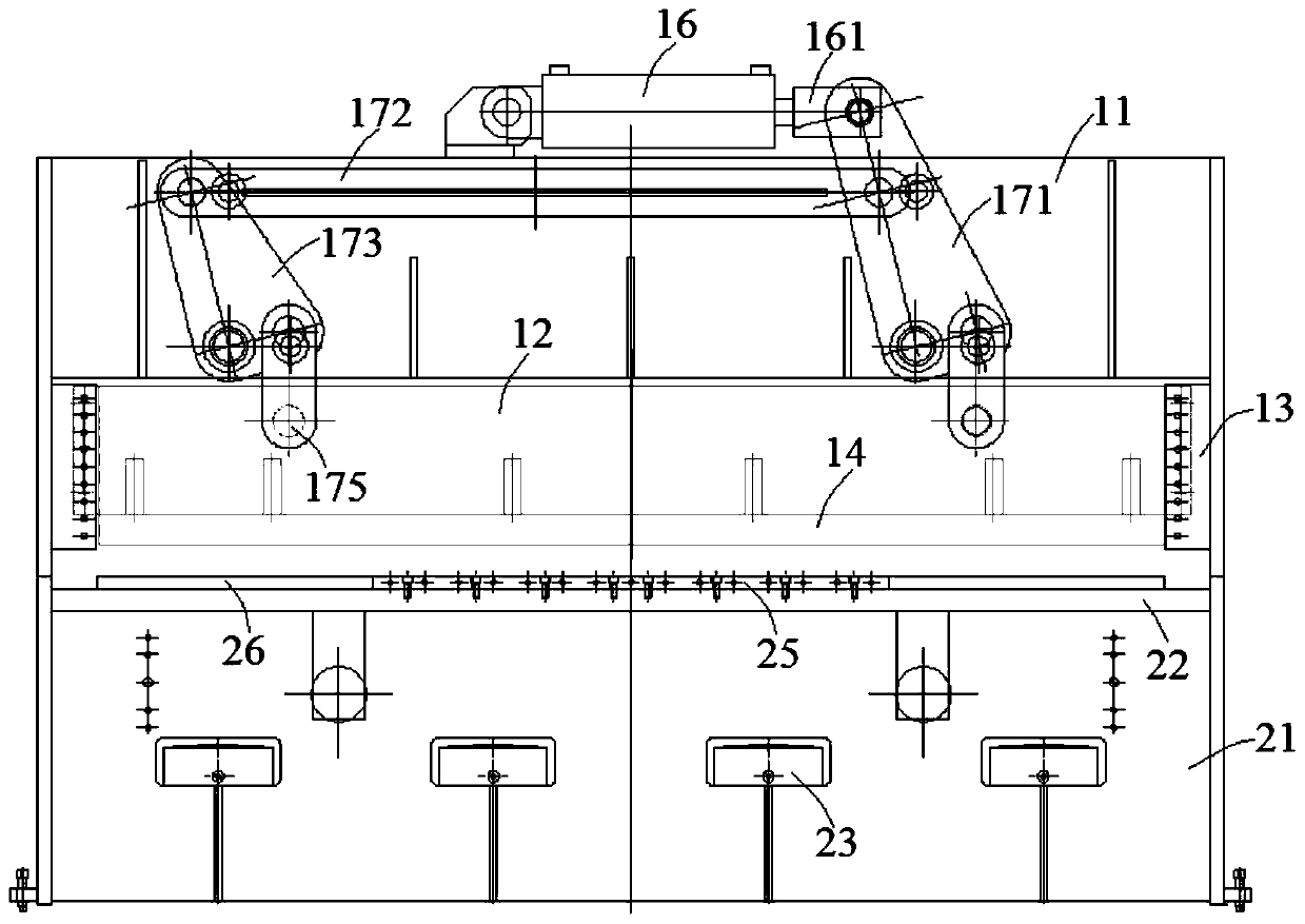
[0049] combine figure 1 and image 3 , a special hydraulic press for container roofs in this embodiment, comprising an upper box body 11, an upper slider 12, an upper mold 15, an upper main cylinder 16, a lower box body 21, a lower main cylinder 23, a lower slider 24 and a lower mold 27 . Described upper master oil cylinder 16 is arranged on upper box body 11 tops, and upper slide block 12 is arranged on upper box body 11 bottoms, and upper mold base 14 is arranged at the bottom of upper slide block 12, and upper mold base 15 is fixed on upper mold base 14.
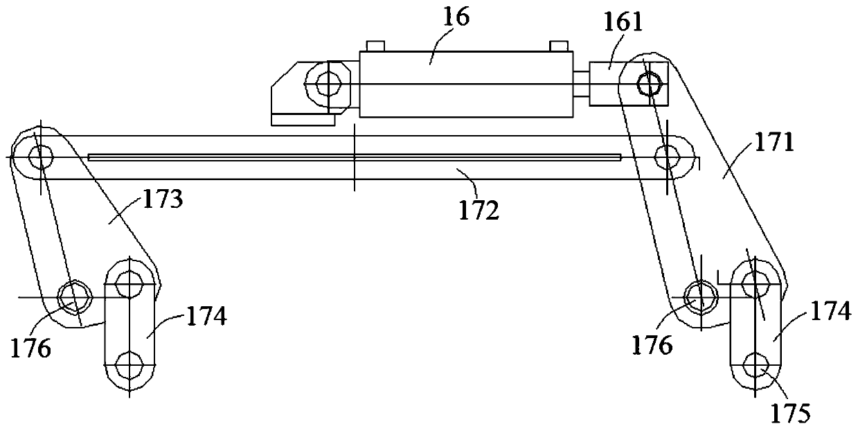
[0050] A drive unit is arranged between the upper master oil cylinder 16 and the upper slider 12, combined with figure 2 , the drive unit includes a main swing link 171, a beam 172, a secondary swing link 173 and a vertical link 174, one end of the beam 172 is connected to the main swing link 171, and the other end is connected to the secondary swing link 173. Both the swing link 171 and the auxiliary swing link 173 ...
Embodiment 2
[0055] combine Figure 5 , Image 6 , Figure 7 and Figure 8 , a special hydraulic press for container roofs in this embodiment is basically the same as in Embodiment 1, except that the design of the upper die 15, the lower die 27 and the blank holder 26 is further optimized in this embodiment, specifically: the upper die is set 15 is a die, and threaded holes are set around the die cavity, and the die is inserted into the threaded holes by bolts to be connected with the upper mold base 14 at the bottom of the upper slide block 12 . The lower die 27 is a convex die, and threaded holes are arranged along the length direction of the lower die 27, and the lower die 27 is inserted into the threaded holes by bolts to be connected with the lower block 24. The upper die 15, the blank holder 26 and the lower die 27 are all designed with a large arc surface along the length direction.
[0056] It is worth noting that, in the initial design of the hydraulic press, the inventor did ...
Embodiment 3
[0058] combine Figure 9 , a special hydraulic press for container roofs in this embodiment is basically the same as in Embodiment 2, the difference is that in this embodiment, a back gauge device is provided on one side of the lower box body 21 in the direction of plate movement, and the back gauge device The traction sheet moves horizontally in one direction. The back gauge device includes a motor 31, a rear support plate 32, a screw rod 33, a sliding seat 341, a finger 346, a front support plate 36 and a sprocket 37, and the front support plate 36 is connected to the lower box 21 through a screw 361 , said screw rod 33 is provided with two, and two screw rods 33 are straddled in parallel between the front support plate 36 and the rear support plate 32, and one end of one of the screw rods 33 is connected with the motor 31, and the other end is provided with a chain Wheel 37; Another screw mandrel 33 one ends also are provided with sprocket wheel 37, and drive chain is set ...
PUM
 Abstract
Description
Claims
Application Information
 - R&D
- Intellectual Property
- Life Sciences
- Materials
- Tech Scout
- Unparalleled Data Quality
- Higher Quality Content
- 60% Fewer Hallucinations
Browse by: Latest US Patents, China's latest patents, Technical Efficacy Thesaurus, Application Domain, Technology Topic, Popular Technical Reports.
© 2025 PatSnap. All rights reserved.Legal|Privacy policy|Modern Slavery Act Transparency Statement|Sitemap|About US| Contact US: help@patsnap.com