Conveying and reversing device for catalyst slurry

A technology of reversing device and catalyst slurry, which is applied in the directions of liquid distribution, conveying or transfer device, distribution device, transportation and packaging, etc., can solve problems such as the decline of catalyst quality and effect, the decline of slurry purity, and the decline of slurry transportation efficiency. , to achieve the effect of maintaining high-efficiency transportation for a long time, improving yield and quality, and ensuring high-efficiency production

Inactive Publication Date: 2018-06-05
程晋军
View PDF7 Cites 1 Cited by
  • Summary
  • Abstract
  • Description
  • Claims
  • Application Information

AI Technical Summary

Problems solved by technology

[0005] (1) In the traditional catalyst slurry delivery device, the catalyst slurry is often in contact with the air during the transportation process. If the slurry is in contact with the air for a long time, the slurry will react with the air, contaminate the slurry, and the purity of the slurry will decrease. The final catalyst quality and effect are greatly reduced;
[0006] (2) Generally, the device for transporting catalyst slurry is a slurry transport pump, which is especially suitable for transporting solutions with high solid particle content. However, due to the abrasion of the pump by the solid matter in the slurry, the service life of the pump and impeller is very short, and the transport The efficiency of the slurry will drop, and the state of high-efficiency transportation cannot be maintained for a long time

Method used


Image

  • Conveying and reversing device for catalyst slurry
  • Conveying and reversing device for catalyst slurry

Examples


Embodiment

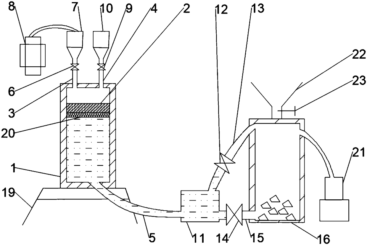
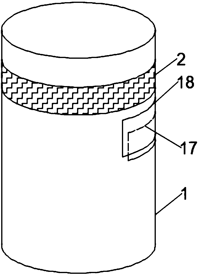
[0024] Such as figure 1 with figure 2 As shown, the present invention provides a reversing device for catalyst slurry delivery, including a piston cylinder 1, a bracket 19 is provided at the bottom of the piston cylinder 1, and the bracket 19 supports the piston cylinder 1, and the bracket 19 makes the piston cylinder 1 Conveying the slurry is more stable. The side of the piston cylinder 1 is provided with a feed port 17, and a sealed door 18 is installed on the outside of the feed port 17. The sealed door 18 covers the feed port 17, and the feed port 17 is convenient for catalyst The slurry enters the piston cylinder 1 and is transported. Here, the feed port 17 is set under the piston 2, that is, when the piston 2 is in a balanced state, the piston 2 is located above the feed port 17, so that the slurry can only fill the space under the piston 2. , the sealing door 18 is a part that seals the piston cylinder 1 after the slurry is filled, so as to avoid that the kinetic ener...


PUM


Abstract

The invention discloses a conveying and reversing device for catalyst slurry. The conveying and reversing device comprises a piston barrel. A piston is installed in the piston barrel. An air inlet pipe and an exhaust pipe are fixedly installed on the top face of the piston barrel. A conveying pipe is fixedly installed on the bottom face of the piston barrel. A compression ejector is fixedly connected to the air inlet pipe through an air inlet valve and is connected with an air compressor. A vacuum ejector is fixedly connected to the exhaust pipe through an air outlet valve. A distribution chamber is fixedly connected to the bottom end of the conveying pipe. A feeding pipe is connected to the top face of the distribution chamber through a feed valve. A recovery pipe is connected to the sideface of the distribution chamber through a recovery valve. A reaction barrel is connected to the feeding pipe. Through sealed connection of all devices in a conveying channel, the slurry is more pure, the yield and quality of catalyst preparation are improved greatly, pressure energy of compressed air is converted into slurry kinetic energy, and thus the purpose of slurry conveying is achieved. Through an anticorrosion layer at the bottom of the piston, the piston is not liable to corrosion, effective conveying is kept for a long time, and high-efficiency production of a catalyst is ensured.

Description

technical field [0001] The invention relates to the technical field of catalyst slurry delivery devices, in particular to a reversing device for catalyst slurry delivery. Background technique [0002] Plant photosynthesis is that plants convert the sun's energy into chemical energy, and plants use inorganic matter to produce organic matter and store energy through photosynthesis. Improving the photosynthetic effect of plants is one of the important ways to increase the yield of crops, and it is of great significance to solve the serious problems of food security and food shortage, the first element of human survival. [0003] In the process of crop cultivation, in order to ensure normal growth rate and enhance the disease resistance of plants, catalysts are used in large-scale planting. In the process of use, it is necessary to control the flow direction of the slurry in and out. The traditional solution includes using a bidirectional input and output pump with forward and ...

Claims


Application Information

Patent Timeline
Patent Type & Authority Applications(China)
IPC IPC(8): B67D7/72B67D7/06B67D7/02
CPCB67D7/0233B67D7/06B67D7/725
Inventor 程晋军
Owner 程晋军
Why Eureka
Try Eureka