Distressing device for integrated circuit lead frame

A technology for integrated circuits and lead frames, which is applied in the field of stress relief devices for integrated circuit lead frames, can solve problems such as low automation, material damage and fracture, and long cycle times, and achieve the effects of convenient transportation, improved work efficiency, and high automation

Inactive Publication Date: 2018-06-05
大连鑫鑫创世科技发展有限公司
View PDF6 Cites 2 Cited by
  • Summary
  • Abstract
  • Description
  • Claims
  • Application Information

AI Technical Summary

Problems solved by technology

[0002] During the production and molding process of metal materials, a large amount of stress often accumulates inside. If the stress cannot be eliminated and released in time, it is easy to cause the formed material to bend in a stress environment, and even cause the material to be damaged and fractured, which greatly affects the metal. The service life of the material is very important to the release of the internal stress of the profile. The current methods of stress release include: natural aging. Slow deformation to release stress, which is a commonly used method in traditional casting technology, the effect is good but the cycle is long; artificial aging is to speed up the aging speed, the casting is heated to a certain temperature in the tunnel kiln and kept for a period of time, and stress relief annealing is carried out. This is a commonly used treatment method for small castings. It has good stress relief effect but high energy consumption; vibration aging releases stress through mutual collision between castings. For large castings, a vibrator can be used to cause resonance to release internal casting stress. However, existing The stress relief device has low efficiency of stress relief and low degree of automation

Method used


Image

  • Distressing device for integrated circuit lead frame
  • Distressing device for integrated circuit lead frame
  • Distressing device for integrated circuit lead frame

Examples


Embodiment Construction

[0018] The following will clearly and completely describe the technical solutions in the embodiments of the present invention with reference to the accompanying drawings in the embodiments of the present invention. Obviously, the described embodiments are only some, not all, embodiments of the present invention.

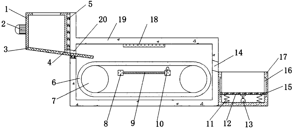
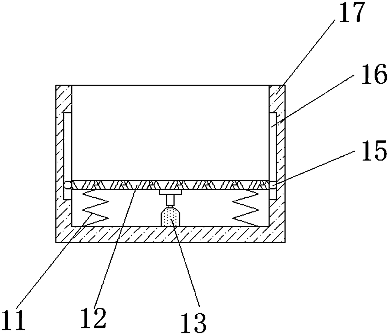
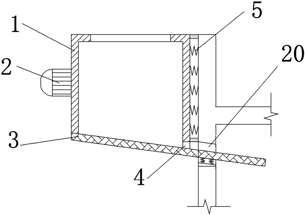
[0019] refer to Figure 1-3 , a stress relief device for an integrated circuit lead frame, comprising a heating box 19, the middle positions of both ends of the inner walls on both sides of the heating box 19 are connected with rollers 7 through bearings, and the circumferential outer walls of the two rollers 7 are sleeved with the same conveyor belt 6. The middle position of the inner wall on the top of the heating box 19 is connected with the second heating resistance plate 18 through fastening bolts, and the middle position of the inner walls on both sides of the heating box 19 is connected with two installation strips 8 through fastening bolts, and the two install...


PUM


Abstract

The invention discloses a distressing device for an integrated circuit lead frame. The distressing device comprises a heating tank, wherein rollers are connected to the middles of two ends of the inner walls on two sides of the heating tank through bearings, the peripheral outer walls of the two rollers are sleeved with the same conveying belt, and a second heating resistor plate is connected to the middle of the inner wall of the top of the heating tank through a fastening bolt. The distressing device is provided with a storage tank, a vibration motor and a first feeding hole, the vibration motor can drive the storage tank and a lead frame in the storage tank to vibrate so as to realize distressing, and materials can be automatically fed into the heating tank through a first feeding hole,so that primary distressing of the lead frame is conveniently and rapidly realized, the movement and transportation of the lead frame is facilitated, and the heating distressing of the lead frame canbe realized; the distressing device is provided with a temperature sensor, so that the temperature in the heating tank can be monitored in real time, and a reciprocating motor can push a placement plate and the lead frame to vibrate up and down so as to finally realize vibration distressing; and by virtue of a heating distressing process and two vibration distressing processes, the distressing working efficiency is increased.

Description

technical field [0001] The invention relates to the technical field of integrated circuits, in particular to a stress relief device for an integrated circuit lead frame. Background technique [0002] During the production and molding process of metal materials, a large amount of stress often accumulates inside. If the stress cannot be eliminated and released in time, it is easy to cause the formed material to bend in a stress environment, and even cause the material to be damaged and fractured, which greatly affects the metal. The service life of the material is very important to the release of the internal stress of the profile. The current methods of stress release include: natural aging. Slow deformation to release stress, which is a commonly used method in traditional casting technology, the effect is good but the cycle is long; artificial aging is to speed up the aging speed, the casting is heated to a certain temperature in the tunnel kiln and kept for a period of time...

Claims


Application Information

Patent Timeline
Patent Type & Authority Applications(China)
IPC IPC(8): C21D9/00C21D10/00
CPCC21D9/0068C21D10/00
Inventor 安鑫鑫白涛
Owner 大连鑫鑫创世科技发展有限公司
Why Eureka
Try Eureka