
Casing automatic grouting device for well cementing

A technology of automatic grouting and casing, which is applied to the valve device of wellbore/well, wellbore/well components, construction, etc. It can solve the problem of inability to achieve upper and lower permeability of the inner cavity, inability to realize automatic grouting, unstable control relationship, etc. problems, to achieve the effect of reducing steps, saving production costs and improving efficiency

Active Publication Date: 2020-11-10
PETROLEUM ENG TECH RES INST CHINA PETROLEUM & CHEM CORP NORTH CHINA OIL & GAS CO +1
View PDF12 Cites 0 Cited by
  • Summary
  • Abstract
  • Description
  • Claims
  • Application Information

AI Technical Summary

Problems solved by technology

[0004] The authorized announcement number is CN205422636U, and the Chinese patent authorized announcement date is 2016.08.03 discloses a self-priming floating hoop, which includes a shell with both ends that can be connected to the casing, and an inner valve seat and a valve seat are arranged in the shell. The flower basket with mesh is connected with the inner valve seat, and the valve core runs through the middle of the flower basket, and an elastic element and a limiting element are arranged between the valve core and the flower basket to connect with the flower basket. The valve core in the housing can be The function of the one-way valve is realized by the action of the elastic element and the limiting element. The elastic element is a spring sleeved on the valve core, and the limiting element is a steel ball clamped on the outer peripheral surface of the valve core. During the process of lowering the casing, The liquid in the drilling well can also enter the upper casing through the hole on the flower basket wall to balance the external pressure in the casing; when there is downward pressure, the valve core will go down, so that the limiting element will fall off, and the elastic element will reset, and the inner valve seat will The through hole is blocked and turned into an ordinary floating hoop, but the problem is that the steel ball is used to block the spring so that it cannot be reset. This control relationship is unstable. When the balls are separated from each other, the restriction of the steel ball to the spring will be invalid, and the spring can be reset, and it is impossible to keep the inner cavity of the shell transparent up and down, so that the function of automatic grouting cannot be realized.

Method used


Image

  • Casing automatic grouting device for well cementing
  • Casing automatic grouting device for well cementing

Examples


specific Embodiment

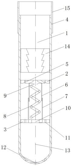
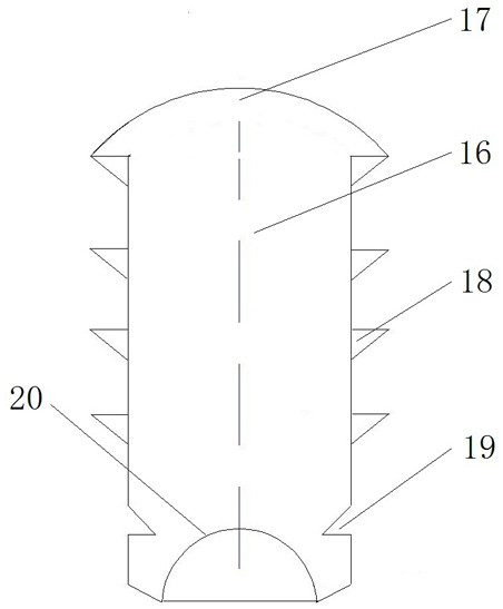
[0031] Such as Figure 1 to Figure 2 As shown, it is a specific embodiment of the automatic casing grouting device for well cementing in the present invention: the automatic casing grouting device for well cementing includes a device main body 1 for mud or drilling fluid or other fluids to pass through, and in the device main body 1 A check valve structure capable of controlling the on-off of the main body 1 of the device is provided. The top 4 of the main body of the device is provided with external threads connected in series with other casings. The bottom 13 of the main body of the device is a shoe structure, which can protect the main body 1 of the device.

[0032]In the middle of the main body 1 of the device, there are two supporting rings parallel to each other, which are the valve block support seat 2 and the spring seat 3 respectively. Both the valve block support seat 2 and the spring seat 3 are provided with central holes for fluid to pass through. Between the valve...


PUM


Abstract

The invention relates to the technical field of oil and gas well cementing devices, and provides an automatic grouting device for a well cementing sleeve. The automatic grouting device for the well cementing sleeve includes a tubular device main body, a single-flow valve assembly is arranged in the device main body, the single-flow valve assembly includes a spring seat, and the spring seat is provided with a spring for abutting against a valve ball to a valve port of the single-flow valve assembly, the valve port is formed by a one-way movable valve seat disposed in the device main body, the one-way movable valve seat includes two or more valve blocks swinging up and down, and the valve blocks have a closed state in which the valve port is formed by mutual closing and an open state for thevalve ball to pass from top to bottom, the top of the spring is provided with a valve ball seat for supporting the valve ball, and the valve ball seat is provided with a ball seat circulating hole communicated with the valve port. The device does not need intermittent operation and has a stable working state during grouting and can reduce the amount of work, improve the work efficiency of the well cementing operation, reduce parts needed during the grouting process and reduce the production cost.

Description

technical field [0001] The invention relates to the technical field of oil and gas well cementing devices, in particular to an automatic casing grouting device for well cementing. Background technique [0002] In oil drilling and cementing operations, technicians usually use empty casing to connect conventional floating hoops and floating shoes into the well. The essence of the floating hoop is a check valve. After being installed on the casing string, it can only allow Positive circulation, the check valve restricts the fluid from pouring back into the casing string. Therefore, in the casing operation, the operation form of intermittent grouting can maintain the pressure balance inside and outside the casing, which is conducive to the entry of the pipe string into the well and prevents the casing from being squeezed Bad. Usually, an oil well needs to use the grouting pipeline for manual grouting many times during the process of running the casing. The operation time is lon...

Claims


Application Information

Patent Timeline
Patent Type & Authority Patents(China)
IPC IPC(8): E21B33/13E21B34/08E21B33/134
CPCE21B33/13E21B33/134E21B34/08E21B2200/04
Inventor 赵文彬张辉张永清王智洪刘颖邓红琳
Owner PETROLEUM ENG TECH RES INST CHINA PETROLEUM & CHEM CORP NORTH CHINA OIL & GAS CO
Learn More