Condensed water desalination water indirect heat exchange exhaust steam recovery primary deaeration device

A waste steam recovery and condensed water technology, which is applied in degassed water/sewage treatment, preheating, supplementary water supply, etc., can solve the problems of aggravated waste heat discharge, large temperature difference between condensed water and desalted water, and reduced back pressure, achieving Exacerbates the effect of waste heat emissions

Active Publication Date: 2016-01-13
云南能投有能科技股份有限公司
View PDF4 Cites 0 Cited by
  • Summary
  • Abstract
  • Description
  • Claims
  • Application Information

AI Technical Summary

Problems solved by technology

[0004] The above recovery methods have the following disadvantages: 1. The deaerator is atmospheric type, and the working temperature is about 104°C, but the actual temperature after mixing the condensed water and desalinated water is far higher than 104°C, so the excess part can only pass through the deaerator head A large amount of flash tank connected to the deaerator is empty, wasting a lot of waste heat and water resources
2. The temperature difference between condensed water and desalinated water is large. It is difficult to achieve a balance of heat in an instant through direct mixing and heat transfer. Therefore, thermal explosion is prone to occur in the deaeration box, which affects the safe operation of the equipment.
3. There is a contradiction between the intermittent water replenishment of the boiler and the continuity of condensed water generation: when the boiler does not replenish water or the amount of water replenished is not large, the valve opening of the calciner condensed water into the deaerator is small, the system pressure is suppressed, and the calciner grate The condensate water is not smooth; when the boiler replenishes a large amount of water, the valve opening of the calciner condensate water into the deaerator is large, the back pressure of the system is reduced, and the calciner steam is connected to the deaerator, which intensifies the discharge of waste heat
4. The volume of the deaeration box is limited, and an effective buffer cannot be formed between the boiler unit and the production unit

Method used


Image

  • Condensed water desalination water indirect heat exchange exhaust steam recovery primary deaeration device
  • Condensed water desalination water indirect heat exchange exhaust steam recovery primary deaeration device
  • Condensed water desalination water indirect heat exchange exhaust steam recovery primary deaeration device

Examples


Embodiment Construction

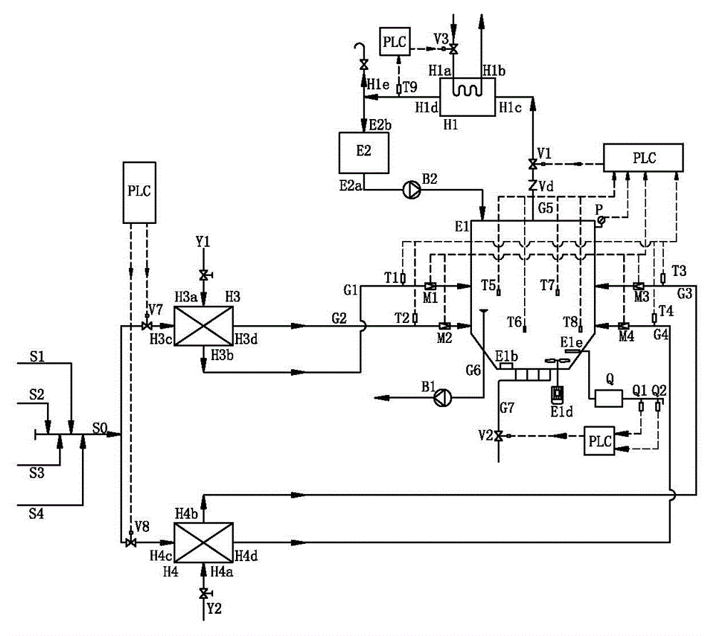
[0030] Such as figure 1 As shown, the condensed water desalination water indirect heat exchange exhaust steam recovery primary deaeration device of the present invention includes a closed pressure buffer tank E1, a third heat exchanger H3 and a fourth heat exchanger H4. The temperature is between 135°C and 155°C. Calciner condensate enters the calciner condensate pipe S1, fluidized bed condensate at 135℃~155℃ enters fluidized bed condensate pipe S2, and dry ammonium condensate at 135℃~155℃ enters dry ammonium condensate pipe, 60℃~80 ℃ Synthetic ammonia cooling and demineralized water enters the synthetic ammonia demineralized water pipe Y1, and the 60℃~95℃ shift cooling demineralized water enters the shift demineralized water pipe Y2. The calciner condensate pipe S1, fluidized bed condensate pipe S2 and dry ammonium condensate pipe S3 are connected respectively Into the condensate collection pipe S0, other condensate pipes S4 can also be connected to the condensate collection pi...


PUM


Abstract

The invention relates to a primary deoxidizing device for performing indirect heat exchange on condensed water and desalted water and recovering exhaust steam. A pressure-bearing buffer tank is provided with first and third water inlet pipes positioned on an upper layer as well as second and fourth water inlet pipes positioned on a lower layer; mixed condensed water is introduced into the second and fourth water inlet pipes respectively after undergoing indirect heat exchange with synthetic ammonia desalted water and transformed desalted water through third and fourth heat exchangers respectively; the synthetic ammonia desalted water and the transformed desalted water are introduced into the first and third water inlet pipes respectively after undergoing heat exchange through the third and fourth heat exchangers; buffer tank exhaust steam enters a first heat exchanger to be cooled into buffer tank exhaust steam condensed water, the buffer tank exhaust steam condensed water is replenished into the pressure-bearing buffer tank through a condensed water collecting tank and a second water pump, and meanwhile non-condensable gas is exhausted; a water outlet pipe of the buffer tank is connected with the inlet of a first water pump; the outlet of the first water pump is connected to a water replenishing pipe of a boiler; a bottom plate of the pressure-bearing buffer tank is connected with a blow-off pipe. The device is high in residual heat utilization ratio of condensed water, and runs reliably.

Description

Technical field [0001] The invention relates to a first-level deoxygenation device for indirect heat exchange exhaust steam recovery of condensed water desalination water, which can be used for the recovery of high-temperature condensate water and heated desalinated water produced in a production line of an alkali plant. Background technique [0002] In order to prevent corrosion of thermal equipment and its pipelines, and prevent non-condensable gases from mixing into steam and degrading steam quality, dissolved oxygen and other non-condensable gases dissolved in boiler make-up water must be removed, often through deaerators. According to Henry's law and Dalton's law, for various gases dissolved in water, under a certain pressure, the higher the temperature of the water, the lower the solubility; or under a certain pressure, the lower the partial pressure of the gas, the gas The lower the solubility. Thermal deaeration is to heat the boiler make-up water to the saturation tempe...

Claims


Application Information

Patent Timeline
Patent Type & Authority Patents(China)
IPC IPC(8): C02F1/20F22D11/06
Inventor 杨晓辉朱成杰黄建伟张国强
Owner 云南能投有能科技股份有限公司
Why Eureka
Try Eureka