

Watertightness and airtightness detection platform
An air-tightness detection and water-tightness technology, applied in the field of detection, can solve the problems of difficulty in finding by workers, misjudgment in detection, and inability to completely determine the leak point, etc., and achieve the effect of speeding up detection.
Active Publication Date: 2018-06-05
重庆晓渝机器人有限公司
View PDF12 Cites 3 Cited by
- Summary
- Abstract
- Description
- Claims
- Application Information
AI Technical Summary
Problems solved by technology
However, when this method is used for detection, since the intake pipe needs to inflate the workpiece, the opening at the joint between the workpiece and the intake pipe is difficult to seal, and the gas is easy to leak from the connection between the intake pipe and the workpiece. leak point
Secondly, after the workpiece is put into the water, the workpiece falls to the bottom of the water under its own gravity, and the bottom of the workpiece is in contact with the bottom of the water. At this time, if tiny air bubbles are generated at the bottom of the workpiece, they will be blocked by the bottom of the workpiece and cannot float up, which is difficult for workers to find
And even if there is a gap in the contact between the workpiece and the bottom of the water, because it is sealed, water cannot enter the inner cavity of the workpiece from the contact, so there is a misjudgment in this detection
Method used
View moreImage
Smart ImageViewing Examples

Examples
Embodiment Construction
[0021] Below in conjunction with accompanying drawing and specific embodiment the present invention will be described in further detail:
Login to View More PUM
 Abstract
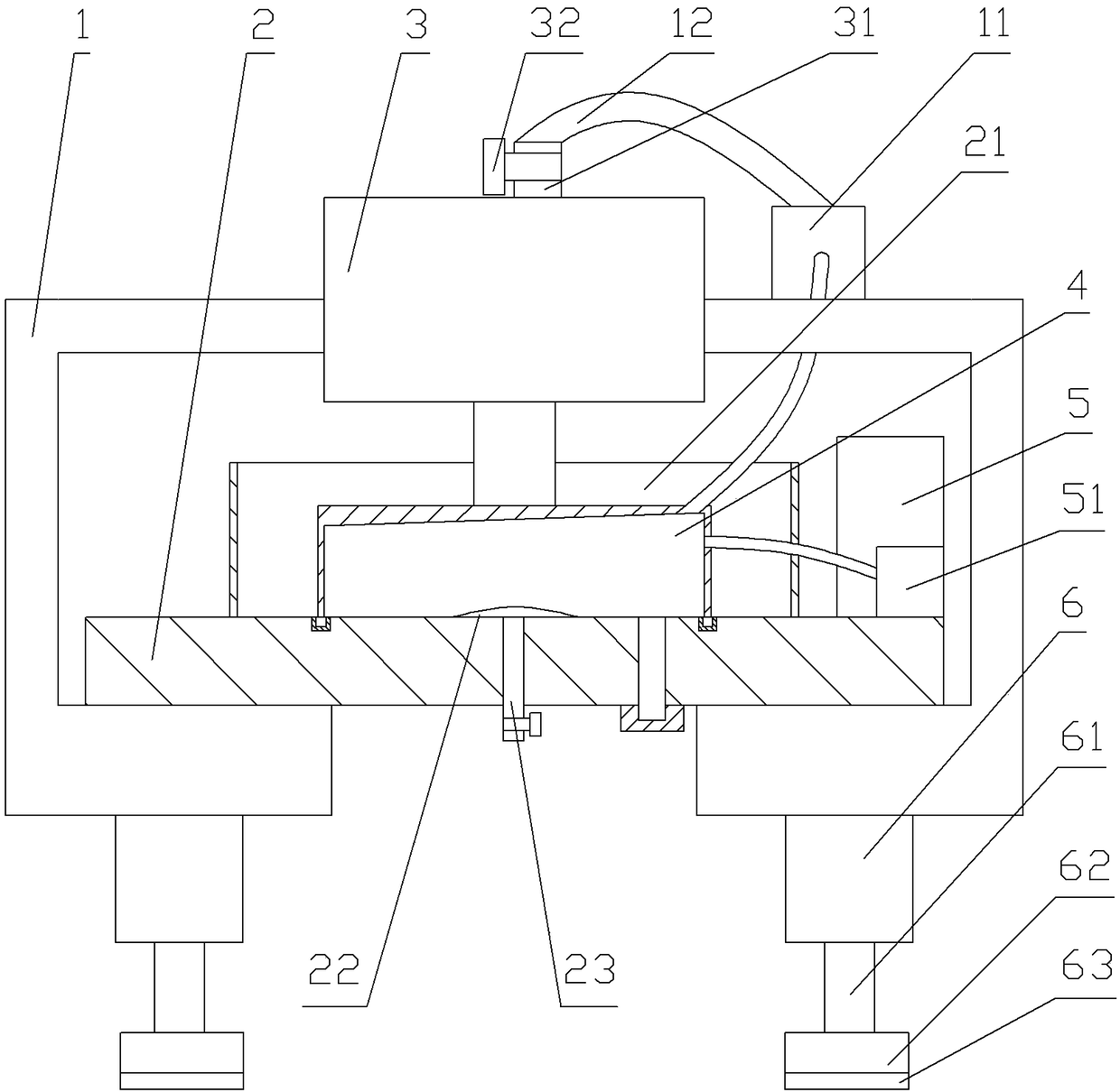
The invention relates to the detection field, and specifically discloses a watertightness and airtightness detection platform. The detection platform comprises a rack, a workbench, a compression mechanism and a water pump. The compression mechanism comprises a sealing cover, an air cylinder and an air pump assembly, wherein the air cylinder and the air pump assembly are fixed on the rack. The aircylinder is provided with an air inlet which can be sealed, and a piston of the air cylinder is fixedly provided with a pressure rod. The sealing cover is fixed on the pressure rod, and the opening ofthe sealing cover faces downwards. The top of the sealing cover is inclined, and the air pump assembly comprises an air incoming pump and an air outgoing pump. The air incoming end of the air incoming pump is communicated with the highest part of the inner cavity of the sealing cover, and the air outgoing end of the air incoming pump is communicated with the air inlet. The air incoming end of theair outgoing pump is communicated with the air cylinder, and the air outgoing end of the air outgoing pump is communicated with the sealing cover. The water pump is communicated with the sealing cover, and the workbench is fixed on the rack. The workbench is fixedly provided with an air bag, a drainage pipe and an annular water blocking barrel, wherein the annular water blocking barrel is locatedat the periphery of the sealing cover. The air bag is communicated with an air incoming pipe which can be sealed, and one end, far from the air bag, of the air incoming pipe passes through the workbench. According to the scheme of the invention, the detection platform can avoid the air leakage or water leakage of an air incoming pipe or a workpiece.
Description
technical field [0001] The invention relates to the detection field, in particular to a water-tightness and air-tightness detection device. Background technique [0002] When the workpiece is cast, after injecting the molten metal into the mold, the mold needs to be cooled so that the molten metal in the mold can be rapidly cooled and formed. However, when the cooling is uneven, cracks are likely to appear on the workpiece, and the cracked workpiece is in use. It is easy to leak air or liquid, so this kind of workpiece is a defective product. However, these cracks are small and difficult to find with the naked eye, so it is necessary to test the watertightness and airtightness of the workpiece. [0003] At present, when performing air tightness testing, the opening of the workpiece is connected to the air intake pipe, and then the workpiece is placed in water, and the air intake pipe inflates the inner cavity of the workpiece to increase the pressure in the inner cavity of ...
Claims
Login to View More Application Information
Patent Timeline
 IPC IPC(8): G01M3/04G01M3/06
CPCG01M3/04G01M3/06
Inventor 张振军
Owner 重庆晓渝机器人有限公司