
Optical fiber tomography method for load distribution monitoring of flexible thin plate structures

A technology of thin plate structure and load distribution, which is applied in the measurement of phase influence characteristics, complex mathematical operations, etc., and can solve the problems of limited number of optical fiber interferometer channels and difficult implementation.

Active Publication Date: 2020-05-19
NANJING UNIV OF AERONAUTICS & ASTRONAUTICS
View PDF4 Cites 0 Cited by
  • Summary
  • Abstract
  • Description
  • Claims
  • Application Information

AI Technical Summary

Problems solved by technology

However, this method requires a large number of optical fiber integrating optical fiber sensors arranged in a criss-cross pattern on the thin plate, and the number of channels of the Mach-Zehnder optical fiber interferometer is limited, which is difficult to implement in engineering

Method used


Image

  • Optical fiber tomography method for load distribution monitoring of flexible thin plate structures
  • Optical fiber tomography method for load distribution monitoring of flexible thin plate structures
  • Optical fiber tomography method for load distribution monitoring of flexible thin plate structures

Examples


Embodiment Construction

[0075] specific implementation plan

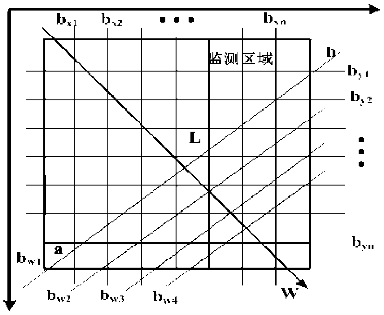
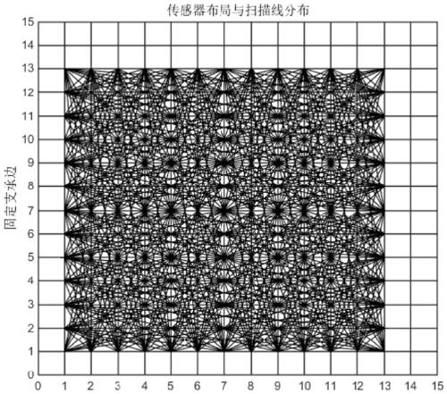
[0076] The purpose of the invention is to introduce the tomographic imaging technology into the distributed optical fiber monitoring and calculation method of the flexible thin plate structure load. This method reconstructs the load distribution of the thin plate structure by arranging a small number of fiber grating sensors and using tomography technology based on Radon transform and its inverse transform.

[0077] 1. In order to solve the above-mentioned technical problems, the optical fiber tomography method for monitoring the load distribution of flexible thin plate structures according to the present invention comprises the following steps:

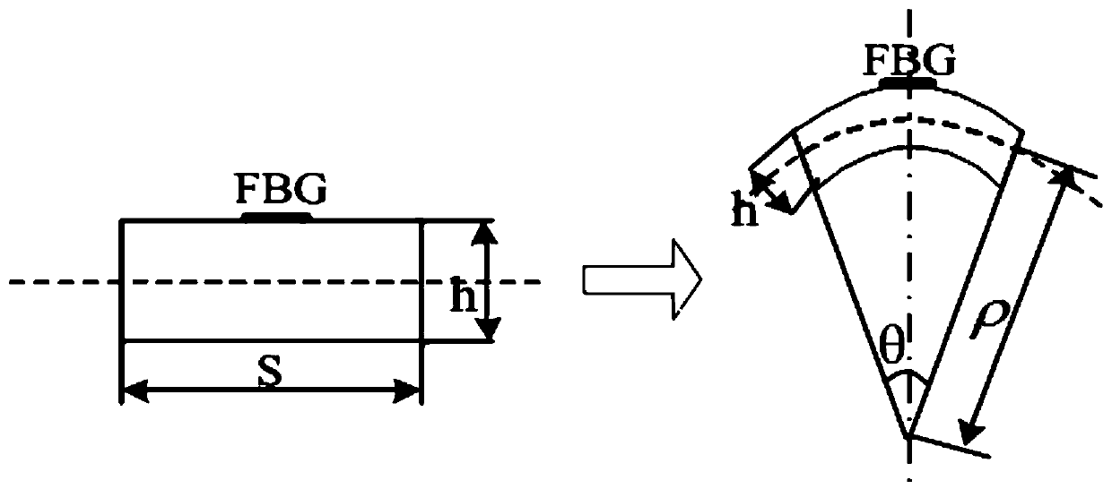
[0078] Step 1. Redefine the microbending mechanical model of the flexible thin plate structure by using the field theory method, and convert the mechanical model into a representation based on operators such as divergence, curl, and gradient;

[0079] According to the micro-bending mechanical mo...


PUM

PropertyMeasurementUnit
thicknessaaaaaaaaaa

Abstract

The invention relates to introduction of a distributed optical fiber sensor and a tomographic imaging technology into monitoring of load distribution of a flexible thin plate structure and belongs tothe field of structural health monitoring. The introduction comprises the following steps: firstly, describing a bending mechanical model of the flexible thin plate structure by adopting a field theory method; secondly, constructing a mechanical model matched with a tomographic imaging method taking Radon conversion as a mathematical foundation; thirdly, adopting a sensor composed of two fiber bragg gratings which are mutually orthogonal in 0 degree / 90 degrees; and according to strain measured by the sensor, calculating spatial second derivative of location deflection where the sensor is located, wherein a difference value of any two spatial second derivatives is namely the Radon conversion of a shear force field; fourthly, according to a principle that a monitored area is covered most widely while the most scanning lines are generated, constructing a sensor observation matrix; fifthly, according to the Radon conversion of the shear force field obtained in the step three, reconstructing the shear force field by adopting Radon inversion; and sixthly, solving divergence of the shear force field, wherein the divergence of the shear force field is namely the load distribution of the flexible thin plate structure.

Description

technical field [0001] The invention belongs to the field of structural health monitoring, and specifically proposes an optical fiber tomographic imaging method for monitoring the load distribution of flexible thin plate structures. Background technique [0002] Load distribution measurement is an important experiment in the research of aircraft aerodynamics. Its purpose is to measure the distribution and change trend of surface loads on various parts of the aircraft, such as wings, empennages, and external stores. It also provides data for the structural strength calculation of the aircraft and its components, as well as aerodynamic load distribution data. [0003] Wings are one of the main components that determine the overall performance of an aircraft. The measurement methods of wing load distribution are: direct measurement method and indirect measurement method. The direct method refers to the pressure measurement method, which is a method of obtaining the aerodynami...

Claims


Application Information

Patent Timeline
Patent Type & Authority Patents(China)
IPC IPC(8): G01N21/45G06F17/13
CPCG01N21/45G06F17/13
Inventor 曾捷潘晓文司亚文朱东方刘鹏张益昕郑丁午周林
Owner NANJING UNIV OF AERONAUTICS & ASTRONAUTICS
Learn More