
Zero-setting device and zero-setting method for anemoscope of large semi-direct-drive unit

An anemometer and semi-direct drive technology, which is applied in the field of the zero-setting device of the anemometer of the large semi-direct drive unit, can solve the problem of affecting the power generation of the unit, the fan cannot be accurately aligned with the incoming wind direction, and the power curve of the generator unit is shifted to the right, etc. problems, to reduce the risk of inaccurate wind, eliminate load imbalance, and achieve the effect of small size

Active Publication Date: 2018-06-08
GUANGDONG MINGYANG WIND POWER IND GRP CO LTD
View PDF9 Cites 2 Cited by
  • Summary
  • Abstract
  • Description
  • Claims
  • Application Information

AI Technical Summary

Problems solved by technology

[0002] At present, the anemometers of wind turbines are manually zeroed during installation and operation and maintenance, such as Figure 6 As shown, the zero scale line of the wind vane is calibrated parallel to the axis of the hub by virtue of the experience of the technicians. It is difficult to make an accurate judgment on whether the zero scale line of the wind vane is parallel to the central axis of the nacelle due to the human senses. If it cannot be aligned with the direction of incoming wind accurately, the inaccurate zero alignment will cause the overall power curve of the generating set to shift to the right, directly affecting the generating capacity of the generating set, such as Figure 7 shown

Method used


Image

  • Zero-setting device and zero-setting method for anemoscope of large semi-direct-drive unit
  • Zero-setting device and zero-setting method for anemoscope of large semi-direct-drive unit
  • Zero-setting device and zero-setting method for anemoscope of large semi-direct-drive unit

Examples


Embodiment Construction

[0040] The present invention will be further described below in conjunction with specific examples.

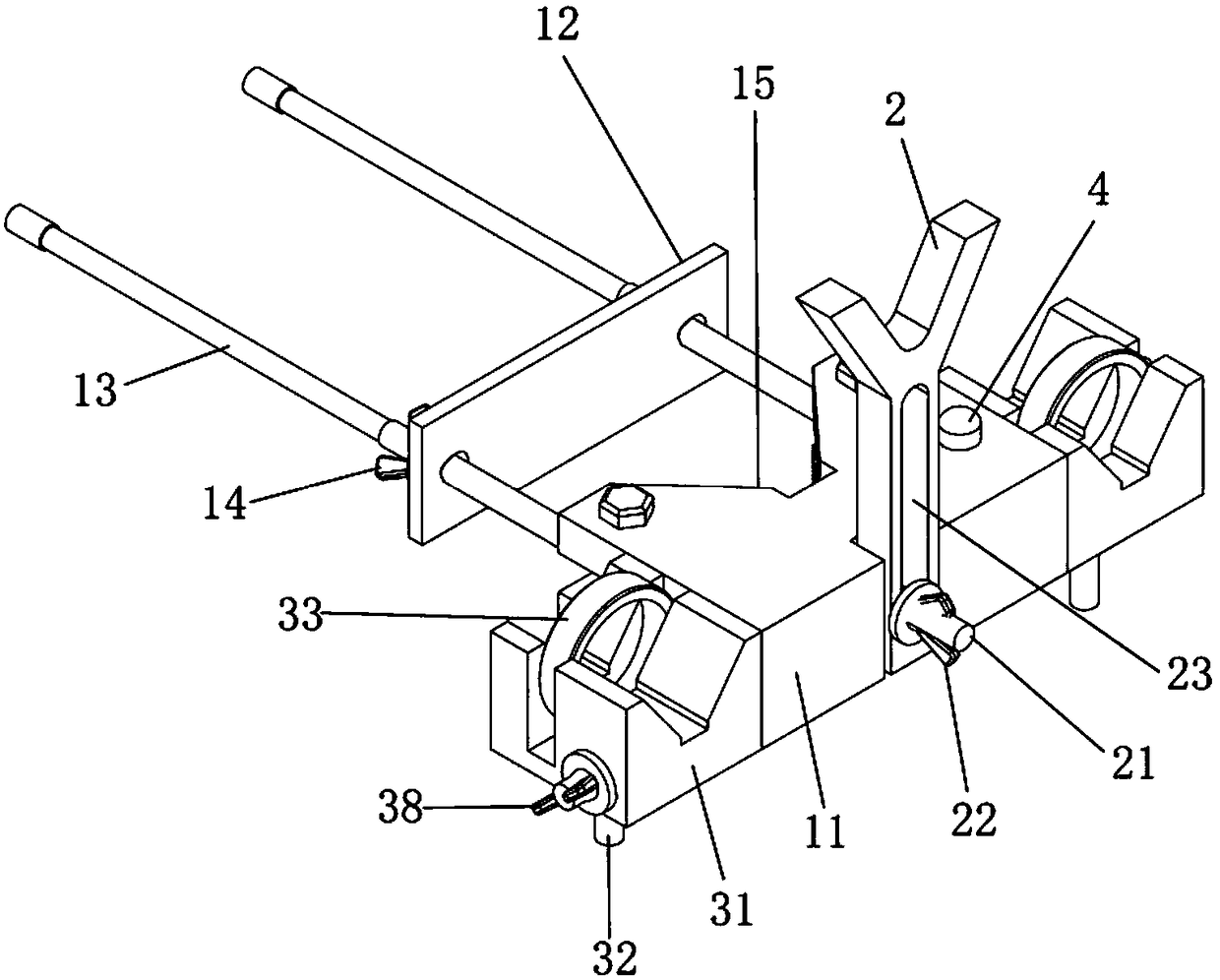
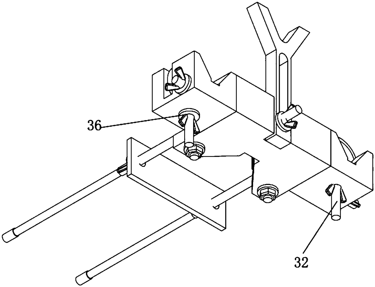
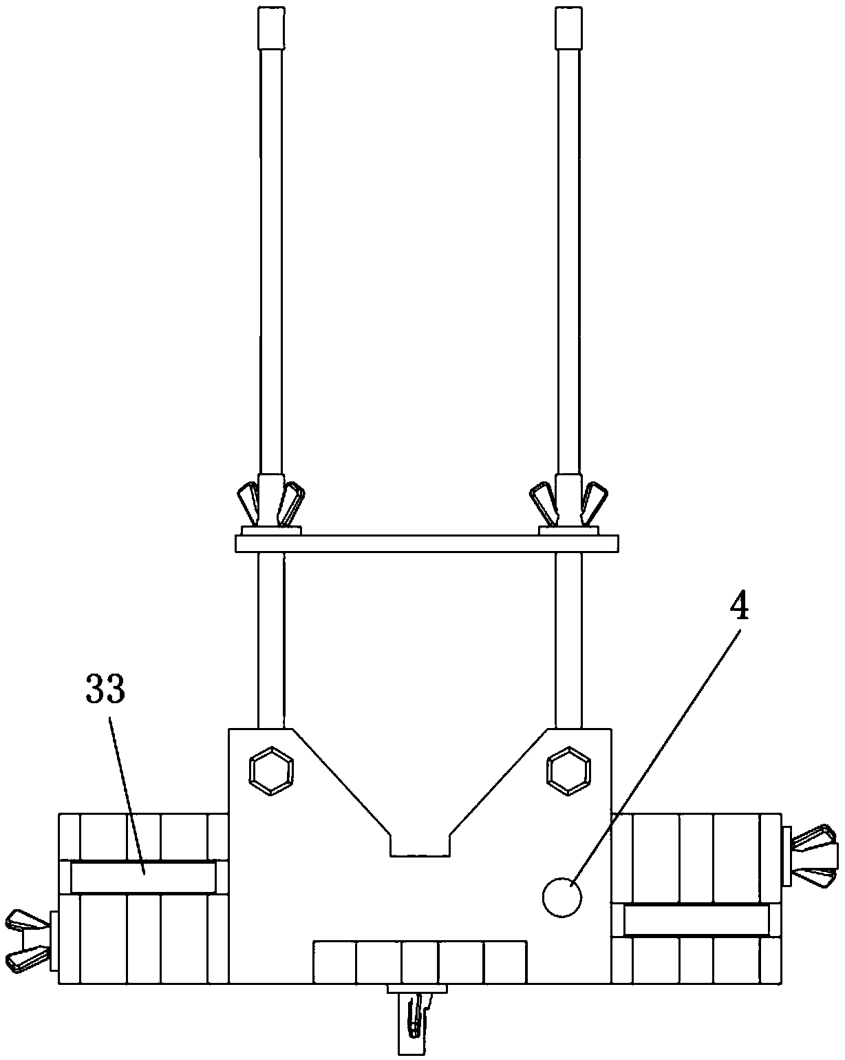
[0041] see Figure 1 to Figure 5 As shown, the zero-setting device for large-scale semi-direct-drive unit anemometer provided in this embodiment includes an anemometer main body clamping mechanism, anemometer counterweight limiting mechanism 2, anemometer laser pen limiting mechanism, a horizontal testing facility. The clamping mechanism of the main body of the anemometer includes a base body 11, a splint 12, a supporting screw rod 13 and a wing nut 14. The front end of the base body 11 has a V-shaped notch 15 for clamping the main body of the anemometer 5 ( That is, the middle cylindrical part of the anemometer), the screw 13 has two symmetrical and vertically installed on the front end of the base, and is located on both sides of the V-shaped notch 15, the splint 12 is sleeved on the two screw 13, can be along the The screw moves, and the base 11, splint 12, and two screw ...


PUM


Abstract

The invention discloses a zero-setting device and a zero-setting method for an anemoscope of a large semi-direct-drive unit. The zero-setting device comprises an anemoscope main body clamping mechanism, an anemoscope counter weight limit mechanism and anemoscope laser pen limit mechanisms, wherein the anemoscope main body clamping mechanism comprises a base body, a clamping plate, and matched screw rods and nuts, a V-shaped notch is formed in the front end of the base body, the screw rods are vertically installed at the front end of the base body, and located at the two sides of the V-shaped notch, and the clamping plate sleeves the screw rods; the anemoscope counter weight limit mechanism is vertically installed at the rear end of the base body of the anemoscope main body clamping mechanism, and a V-shaped intersection structure is formed in the top of the anemoscope counter weight limit mechanism, and used for placing a counter weight part of the anemoscope; and the anemoscope laserpen limit mechanisms are installed at the two sides of the base body of the anemoscope main body clamping mechanism separately, and used for accurately locating a laser pen of the anemoscope. The zero-setting device disclosed by the invention is simple in structure, flexible to operate, and capable of being flexibly used according to the field condition, and guaranteeing that a fan unit can be accurately aligned with a windward direction, thereby improving the performance of the unit and increasing the economic benefits of the unit.

Description

technical field [0001] The invention relates to the technical field of installing and zeroing an anemometer of a wind power generating set, in particular to a zeroing device and a zeroing method for an anemometer of a large semi-direct drive unit. Background technique [0002] At present, the anemometers of wind turbines are manually zeroed during installation and operation and maintenance, such as Image 6 As shown, the zero scale line of the wind vane is calibrated parallel to the axis of the hub by virtue of the experience of the technicians. It is difficult to make an accurate judgment on whether the zero scale line of the wind vane is parallel to the central axis of the nacelle due to the human senses. If it cannot be aligned with the direction of incoming wind accurately, the inaccurate zero alignment will cause the overall power curve of the generating set to shift to the right, directly affecting the generating capacity of the generating set, such as Figure 7 shown....

Claims


Application Information

Patent Timeline
Patent Type & Authority Applications(China)
IPC IPC(8): B23P19/10
CPCB23P19/10Y02E10/72
Inventor 蔡文军牛志雄李晓伟孙安平张蔷李永战
Owner GUANGDONG MINGYANG WIND POWER IND GRP CO LTD
Learn More