High-damping direct-acting-type overflow valve

A direct-acting overflow valve and high damping technology, which is applied in the direction of fluid pressure actuators, servo motor components, mechanical equipment, etc., can solve problems such as noise, reduce the service life of working components, and vibration of the valve core, and achieve reduction Small overall volume, reduced required stiffness, and guaranteed stability

Active Publication Date: 2018-06-08
北京市捷瑞特弹性阻尼体技术研究中心
View PDF16 Cites 4 Cited by
  • Summary
  • Abstract
  • Description
  • Claims
  • Application Information

AI Technical Summary

Problems solved by technology

Although the direct-acting relief valve has the advantages of simple structure and high sensitivity, but because it does not have multiple dampers like the pilot-operated relief valve, the valve core will usually vibrate when the inlet pressure fluctuates greatly, thus causing howling , causing greater damage to the valve seat and spring; in addition, in large flow applications, in order to ensure that the overflow flow will not have a great impact on the regulating pressure, the hole diameter of the valve seat must be large, so the pressure regulating spring Usually the rigidity of the design is very large, resulting in the overall direct-acting relief valve volume is too large
[0003] For example, the application number is 201310162724.1, and the invention patent named "a direct-acting relief valve" discloses a direct-acting relief valve, which mainly includes a valve sleeve, a valve seat, a cone valve core, a pressure spring, a pressure regulating The device and the first seal, although the invention has a simple structure and directly controls the inlet pressure through the cone valve core and the pressure spring, but it lacks damping elements. In the case of inlet flow and pressure fluctuations, the cone valve core will be in a state of up and down vibration , causing system pressure fluctuations, noise and reducing the service life of its working components

Method used


Image

  • High-damping direct-acting-type overflow valve
  • High-damping direct-acting-type overflow valve
  • High-damping direct-acting-type overflow valve

Examples


Embodiment Construction

[0021] The present invention will be further described in detail below in conjunction with the accompanying drawings and embodiments.

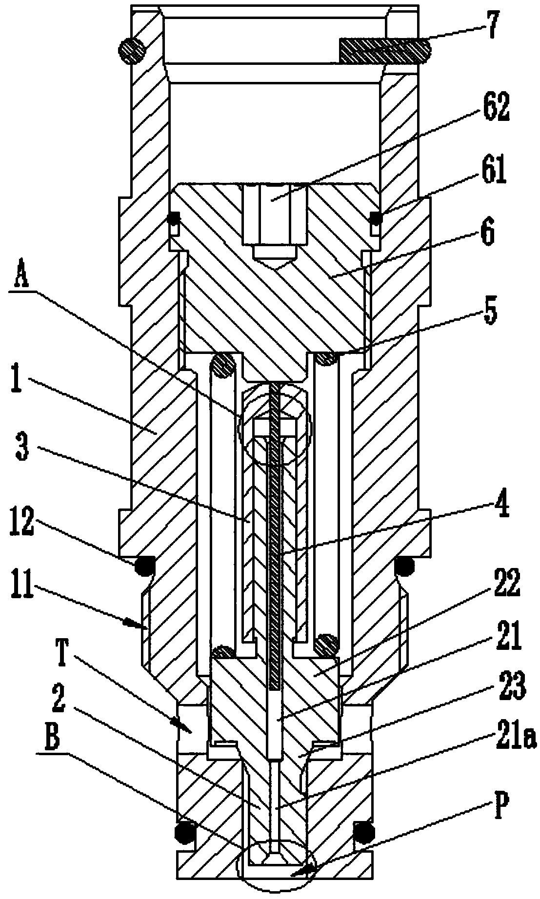
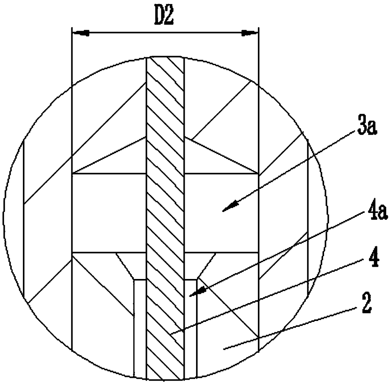
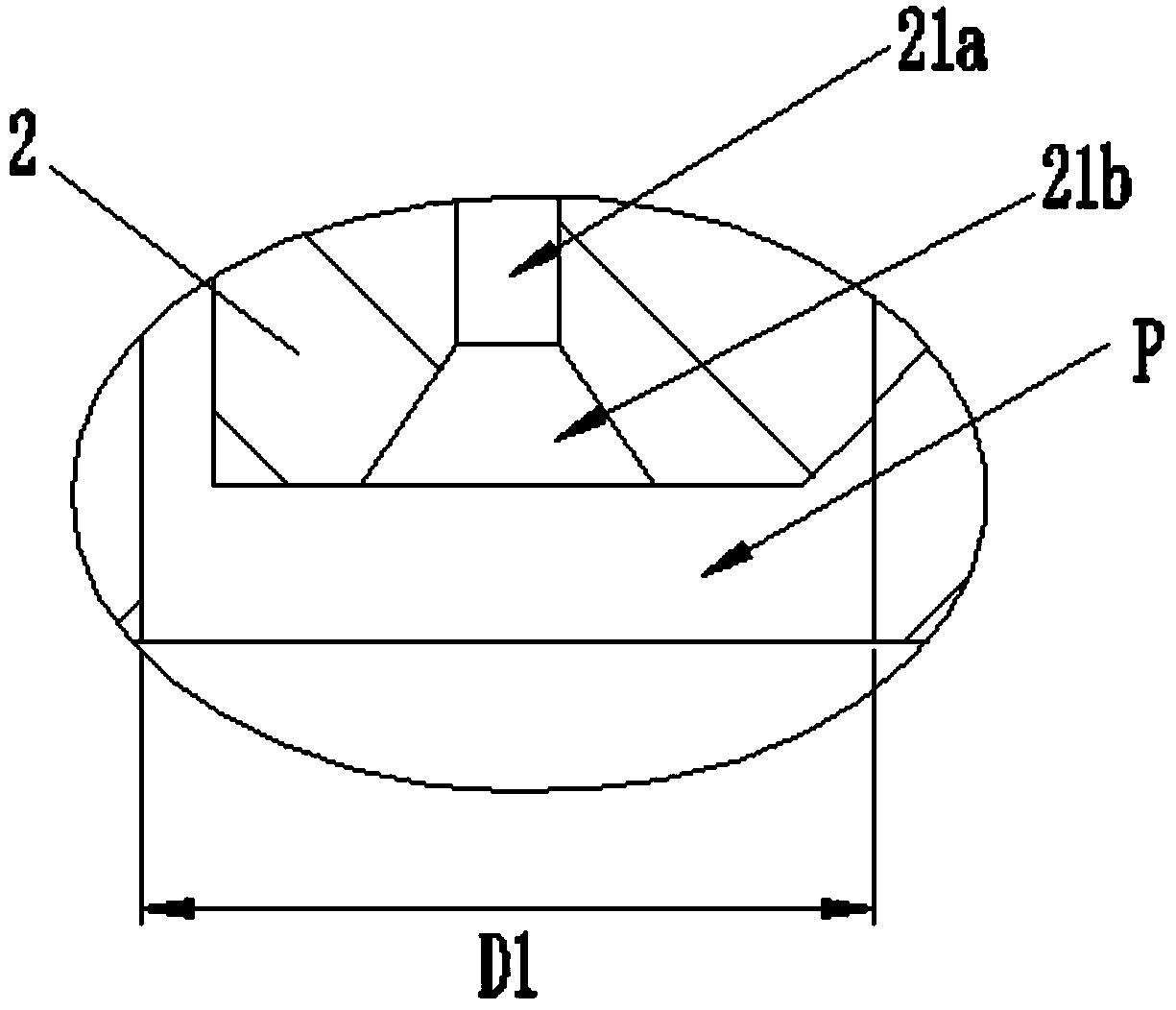
[0022] Such as Figure 1 to Figure 3 Shown is the structural representation of the present invention,

[0023] The reference signs are: P port, T port, valve body 1, external thread 11, valve body sealing ring 12, valve core 2, flow hole 21, reduced diameter section 21a, tapered hole 21b, convex body 22, Tapered part 23, damping sleeve 3, damping chamber 3a, damping plunger 4, damping gap 4a, spring 5, pressure regulating bolt 6, bolt sealing ring 61, inner hexagonal hole 62, limit retaining ring 7.

[0024] Such as Figure 1 to Figure 3 as shown,

[0025] A high-damping direct-acting overflow valve includes a valve body 1, a P port is vertically opened at the lower end of the valve body 1, a T port is opened on the lower side wall of the valve body 1, and a P port is formed between the P port and the T port. There is a valve port, the val...


PUM


Abstract

The invention discloses a high-damping direct-acting-type overflow valve. The high-damping direct-acting-type overflow valve comprises a valve body, an opening P is vertically formed in the lower endof the valve body, an opening T is formed in the side wall of the lower portion of the valve body, a valve opening is formed by the opening P and the opening T, a valve core which cooperates with thevalve opening is vertically arranged in the valve body, a through-flow hole is formed in the center of the valve core, a damping cover sleeves the upper portion of the valve core, a damping plunger isarranged in the center of the damping cover and is inserted into the through-flow hole, a damping gap is reserved between the outer wall of the damping plunger and the inner wall of the through-flowhole, a damping cavity is formed by the upper end face of the valve core and the damping cover and is communicated with the opening P through the through-flow hole, and a spring which cooperates withthe valve core is arranged outside the damping cover. The high-damping direct-acting-type overflow valve has the advantages that the structure is compact, pressure generated by the damping cavity is utilized, the rigidity needed by the spring is greatly reduced while the overflowing capacity of the valve is guaranteed, and thus the overall size of the valve is greatly reduced; meanwhile, the damping cavity is utilized for oil pressure adjustment, and the stability during starting and closing can be guaranteed.

Description

technical field [0001] The invention relates to the technical field of overflow valve manufacturing, in particular to a high-damping direct-acting overflow valve. Background technique [0002] Relief valve is a commonly used pressure control component in hydraulic system, which can be used as constant pressure relief valve or safety valve. Relief valves are usually used in pressure control, and the existing relief valves can be divided into direct-acting relief valves and pilot relief valves according to their different structures and working principles. Although the direct-acting relief valve has the advantages of simple structure and high sensitivity, but because it does not have multiple dampers like the pilot-operated relief valve, the valve core will usually vibrate when the inlet pressure fluctuates greatly, thus causing howling , causing greater damage to the valve seat and spring; in addition, in large flow applications, in order to ensure that the overflow flow wil...

Claims


Application Information

Patent Timeline
Patent Type & Authority Applications(China)
IPC IPC(8): F15B13/02
CPCF15B13/024
Inventor 陈艳艳
Owner 北京市捷瑞特弹性阻尼体技术研究中心
Why Eureka
Try Eureka