A test device for determining the electromagnetic properties of an object under test

A technology for testing devices and objects under test, which is applied in the directions of electromagnetic field characteristics, measuring device casings, etc., to achieve the effect of simple and convenient sampling process, reliable testing results, and reducing probe damage.

Active Publication Date: 2019-12-06
SUNYIELD TECH CO LTD
View PDF6 Cites 0 Cited by
  • Summary
  • Abstract
  • Description
  • Claims
  • Application Information

AI Technical Summary

Problems solved by technology

As we all know, as a planar near-field scan, in order to effectively derive the far field within a certain range, it must be sampled in the entire plane, and the sampling point spacing must be satisfied L

Method used


Image

  • A test device for determining the electromagnetic properties of an object under test
  • A test device for determining the electromagnetic properties of an object under test
  • A test device for determining the electromagnetic properties of an object under test

Examples


Embodiment 1

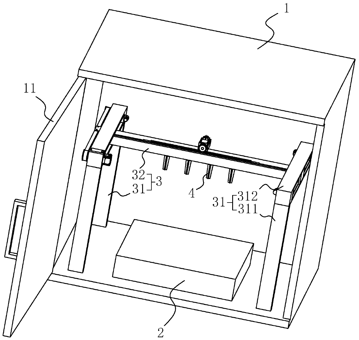
[0035] Embodiment 1: a kind of testing device for determining the electromagnetic performance of the object under test, such as figure 1 As shown, a box cover 11 is hinged on the box body 1, and the box cover 11 covers the box body 1 to form a closed detection space. In other embodiments, if the plane near-field test site has a darkroom or a shell with shielding function Body, the box body 1 may not be provided; the bottom of the box body 1 is fixed with a stage 2 for placing the measured object, and the two sides of the stage 2 are provided with brackets 3;

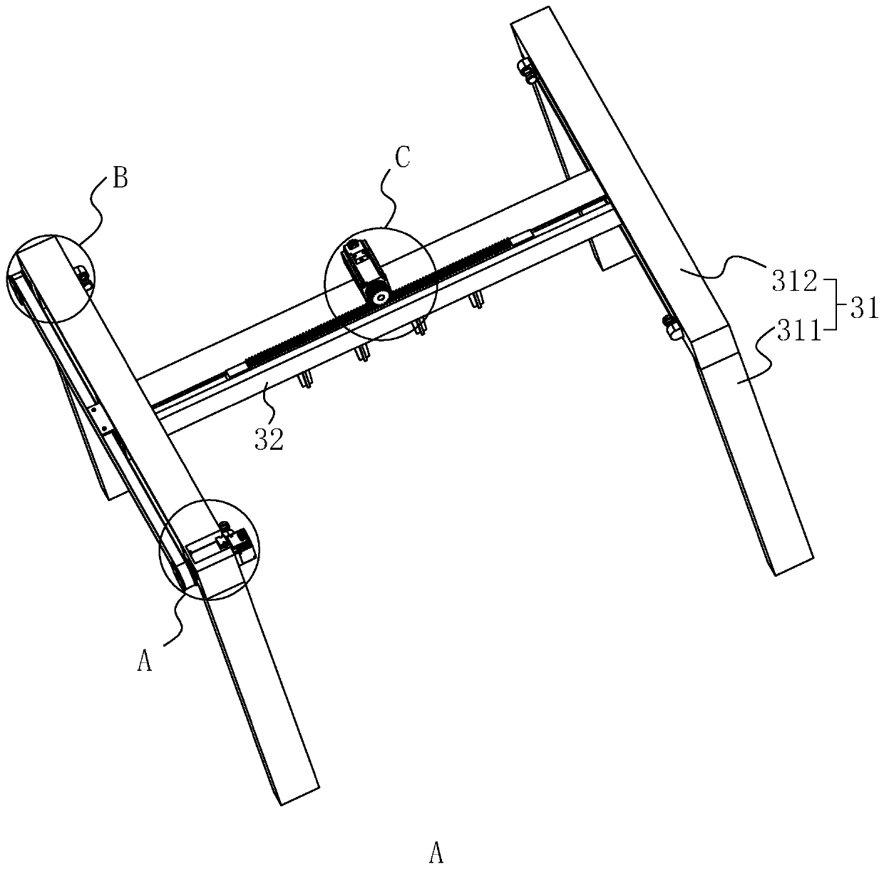
[0036] Such as figure 1 As shown, the support 3 includes a stand 31 arranged on both sides of the object stage 2 and a sliding rod 32 slidably connected to the stand 31, and the stand 31 is welded to the vertical rod 311 and the welding vertical rod 311 at the bottom of the box body 1 Composed of a cross bar 312 on the top of the cross bar 312, a notch for the sliding of the sliding rod 32 is opened, and a slider is fix...

Embodiment 2

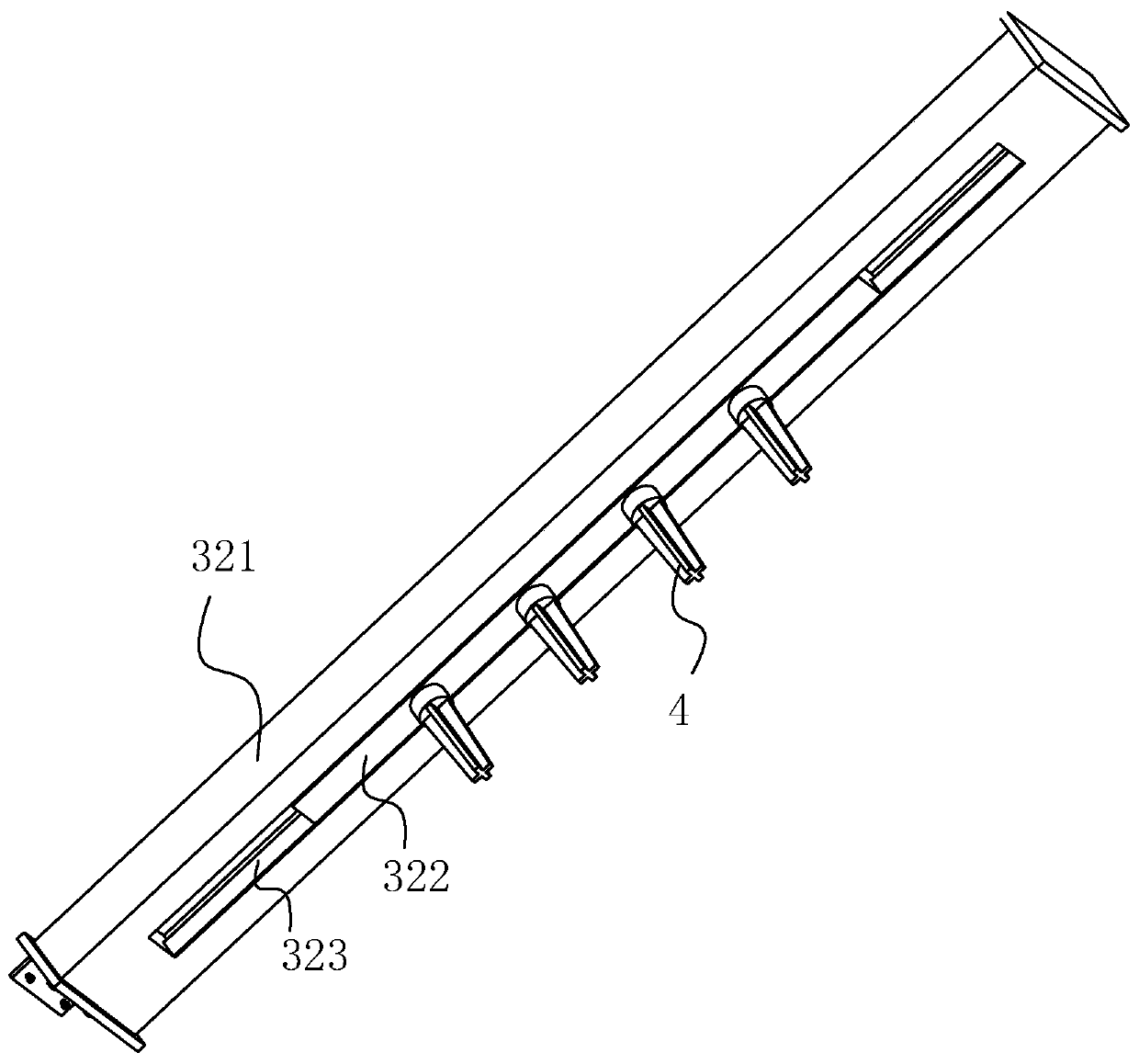
[0044] Embodiment two: a kind of testing device for determining the electromagnetic performance of the object under test, such as Figure 9 and Figure 10 As shown, the difference from Embodiment 1 is that the limit assembly includes a limit protrusion 86 fixed on the inner rod 322, and the limit protrusion 86 is located near the outermost probe 4 and passes through the sliding groove 323 to Downward extension; in order to reduce the phenomenon that the rigid contact between the position-limiting protrusion 86 and the stand 31 causes damage to the position-limiting protrusion 86 and the stand 31, fix on the side of the position-limiting protrusion 86 facing the stand 31 There is a second elastic member 87, the second elastic member 87 adopts a spring, and the second elastic member 87 is aligned with the cross bar 312, so that when the outermost probe 4 is located near the stand 31, the second elastic member 87 can Collision on the crossbar 312;

[0045] When the inner rod 32...


PUM


Abstract

A testing apparatus for determining the electromagnetic performance of a tested object, comprising a housing (1), an object supporting platform (2), and a support frame (3). The support frame (3) comprises upright frames (31), a sliding rod (32), and multiple probes (4) provided in the axial direction of the sliding rod (32), also comprises a transverse driver apparatus used for driving the sliding rod (32) to move along the upright frames (31) and an axial driver apparatus (6) used for driving the multiple probes (4) to concurrently move in the axial direction of the sliding rod (32). With the multiple probes being used, each time when multiple points on a plane are scanned, by means of two moving apparatus, a quick scanning method is provided for rapidly constructing a planar field, thus implementing the advantages of the oversampling of a tested object, a simplified and convenient sampling process, increased density of sampled data point distribution, and increased reliability of test results.

Description

technical field [0001] The invention relates to the technical field of antenna testing, more specifically, it relates to a testing device for determining the electromagnetic performance of a measured object. Background technique [0002] When testing the electromagnetic performance of the antenna, it is necessary to detect multiple points of the object under test, and test multiple sets of data so that the electromagnetic performance of the object under test can be more comprehensively reflected. In order to improve the accuracy of the test results, Usually, an oversampling method is used to detect the measured object. As we all know, as a planar near-field scan, in order to effectively derive the far field within a certain range, it must be sampled in the entire plane, and the sampling point spacing must be satisfied L<lambda / 2, where lambda is the wavelength of the radiation signal; and the current oversampling The method is only generally used in the spherical near fi...

Claims


Application Information

Patent Timeline
Patent Type & Authority Patents(China)
IPC IPC(8): G01R29/08G01R1/04
CPCG01R1/04G01R29/08
Inventor 韩栋
Owner SUNYIELD TECH CO LTD
Why Eureka
Try Eureka