Eureka AIR delivers breakthrough ideas for toughest innovation challenges, trusted by R&D personnel around the world.

Filter device for an oil filter

A technology of filter device and filter layer, applied in fixed filter element filter, filter separation, membrane filter, etc., can solve the problem that oil cannot pass through filter medium, etc., achieve high flexibility, increase filter volume, and improve filter efficiency.

Active Publication Date: 2018-06-08
IBS FILTRAN KUNST METALLERZEUGNISSE
View PDF7 Cites 0 Cited by
  • Summary
  • Abstract
  • Description
  • Claims
  • Application Information

AI Technical Summary

Problems solved by technology

Another disadvantage of the filter medium known from EP 2133130 A1 is that so-called dead surfaces are formed in the contact area of ​​the filter medium with the first filter layer and the second filter layer, so that oil cannot pass through the filter medium because the frame element itself Structure impervious to oil

Method used


Image

  • Filter device for an oil filter
  • Filter device for an oil filter

Examples


Embodiment Construction

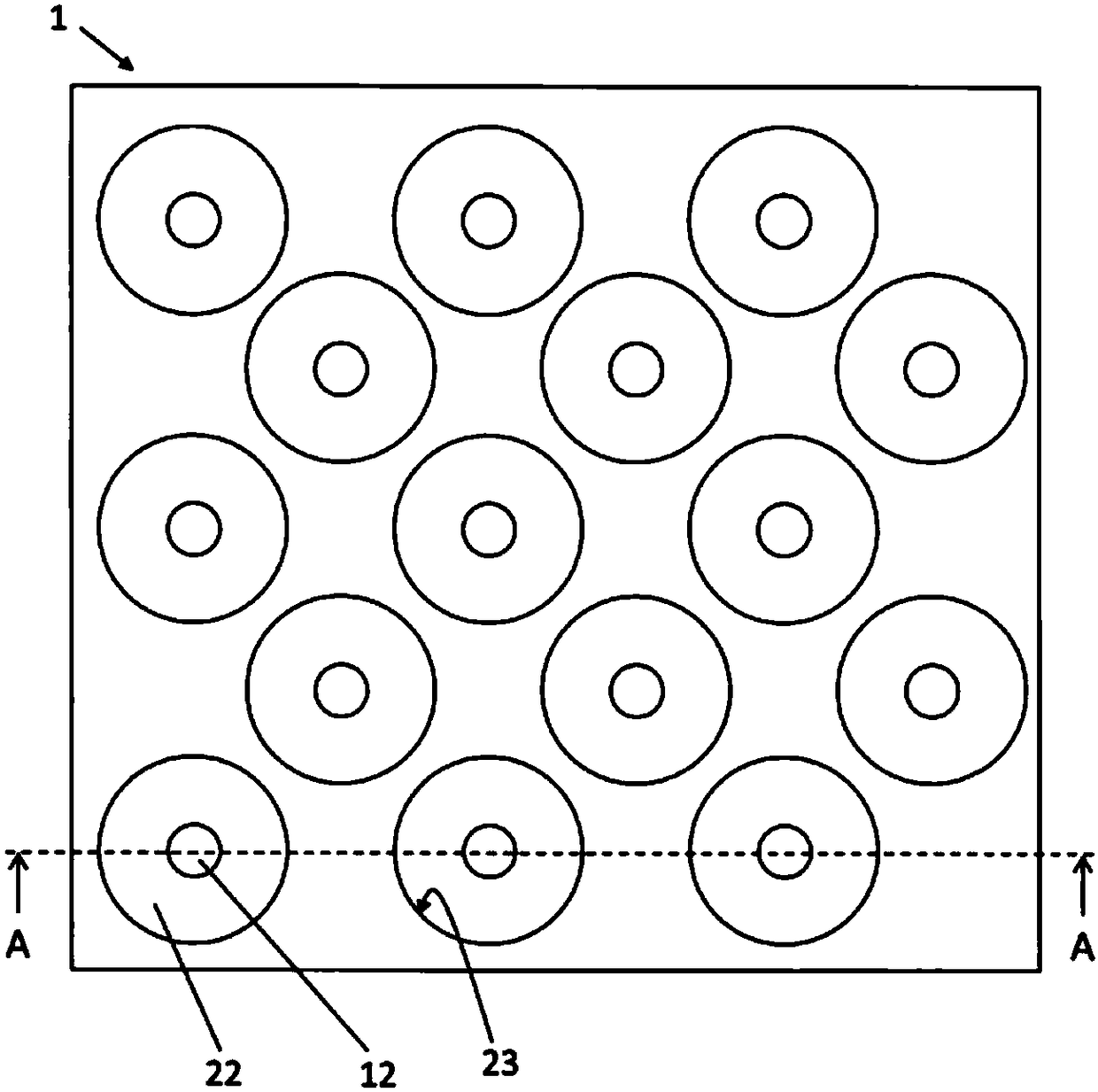
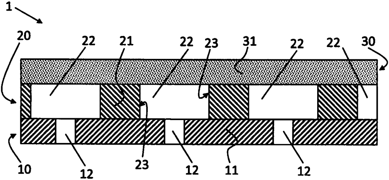
[0035] figure 1 is a plan view of a filter device 1 according to the invention, which filter device 1 may also be referred to as a filter medium 1, and figure 2 yes figure 1 A schematic sectional view of the filter device 1 shown in , along the plane of section A-A. In this case, it should be noted that the figure 1 The second filter layer 30 is not shown, so that from figure 1 Only the frame element 20 of the filter device 1 and the plan view of the first filter layer 10 below it can be seen, while in figure 2 The second filter layer 30 arranged on the frame element 20 can also be seen in FIG.

[0036] As described above, the filter device 1 for filtering oil according to the present invention includes the first filter layer 10 , the frame member 20 disposed on the first filter layer 10 and the second filter layer 30 disposed on the frame member 20 . The frame element 20 is thus arranged in a sandwich-like manner between the first filter layer 10 and the second filter ...


PUM


Abstract

The present invention relates to a filter device (1) for filtration of oil, comprising a first filtration layer (10), a second filtration layer (30), and a frame element (20), wherein - the frame element (20) is arranged in a sandwich-like manner between the first filtration layer (10) and the second filtration layer (30), and wherein - the frame element (20) has a multitude of passage orifices (22), such that a number of intermediate chambers (22) corresponding to the multitude of passage orifices (22) is formed between the first filtration layer (10) and the second filtration layer (30), wherein the filter device (1) is characterized in that the frame element (20) comprises an oil-permeable filter medium, by means of which filtration of the oil passing therethrough is affected.

Description

technical field [0001] The invention relates to a filter device for filtering oil. Furthermore, the invention relates to a suction filter and a press filter with corresponding filter devices. Background technique [0002] Filter devices known from the prior art, also commonly referred to as filter media, are used for filtering oil, for example in suction filters for cars, trucks and / or motorcycles. [0003] The problem with filter devices or filter media known from the prior art is that, when using highly efficient filter media, there is a considerable pressure loss, especially at low temperatures, for example in the case of a cold start. The reason for this disadvantage is the high viscosity of the oil at low temperatures. Depth filter media that may have acceptable pressure loss and high adsorption capacity will have lower filtration efficiencies. Fabrics for filtration purposes known in the prior art have only a low dirt absorption capacity and have not yet achieved hi...

Claims


Application Information

Patent Timeline
Patent Type & Authority Applications(China)
IPC IPC(8): B01D29/01B01D29/58F01M1/10F01M11/03
CPCB01D29/01B01D29/58B01D2201/0415F01M1/10F01M11/03B01D2201/188
Inventor M·德德林
Owner IBS FILTRAN KUNST METALLERZEUGNISSE
Why Eureka
Eureka Blog
Learn More