Component, provided with a thread

A thread and component technology, which is applied in the field of threaded components, can solve the problems of reducing thread engagement and load capacity, and achieves the effects of easy movement, simplified finishing process, and simple rotation

Inactive Publication Date: 2018-06-08
SIEMENS AG
View PDF6 Cites 0 Cited by
  • Summary
  • Abstract
  • Description
  • Claims
  • Application Information

AI Technical Summary

Problems solved by technology

However, this may involve cost- and compatibility-related issues, since specific cutting tools must be used; moreover, this reduces thread engagement and thus load-carrying capacity (stripping resistance)

Method used


Image

  • Component, provided with a thread
  • Component, provided with a thread
  • Component, provided with a thread

Examples


Embodiment Construction

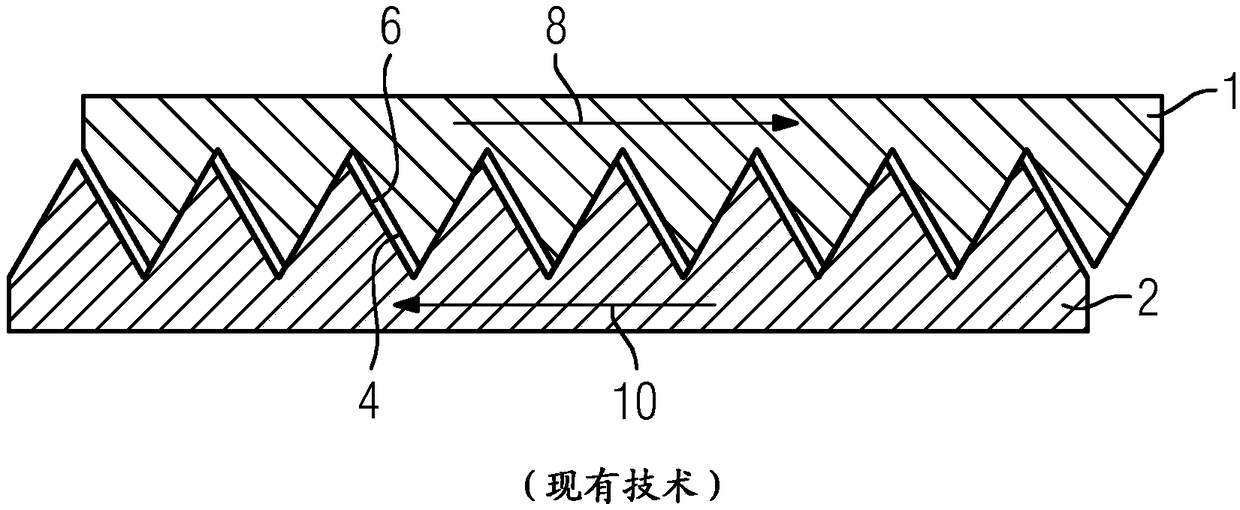
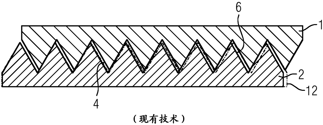
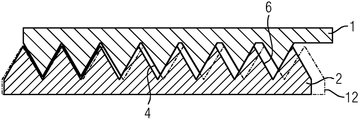
[0030] figure 1 A schematic partial longitudinal section through the upper part of the screw connection is shown. The profiles of two threaded fittings, namely nut 1 and bolt 2, are shown. The threads 4 and 6 of the nut 1 are configured as standard threads, ie according to metric ISO standard threads (DIN 13 and DIN 14), threads according to the unified thread standard (ANSI / ASME B1.1-2003), or Whitworth threads. In any case, in such threads 4 , 6 there is no definite situation of Δxmin provided. In contrast, the axial play Δxmin is produced only by the production-related tolerance range of the pitch circle diameter. Arrows 8, 10 indicate the direction of loading of the nut 1 and the bolt 2.

[0031] The nut 1 and bolt 2 described here are designed for particularly high loads. In an exemplary embodiment, the bolt 2 may be arranged, for example, at the end of a shaft of a gas turbine (not shown in more detail), so that it is coaxial with said shaft and can fix the shaft and...


PUM


Abstract

The invention aims to provide a component (1, 2), provided with a thread (4, 6) that has increased play (delta) in the axial direction in comparison with a standard thread, which allows nuts to be screwed on, even in the case of highly preloaded bolts, and also enables a highly loadable threaded connection. For this purpose, the play (delta) is monotonically increasing in the axial direction.

Description

technical field [0001] The invention relates to a component provided with a thread which has a greater clearance in the axial direction than a standard thread. The invention also relates to a method for finishing a standard thread of a component, wherein greater play is introduced in the axial direction. Background technique [0002] In various technical fields, bolts under particularly high loads are usually stretched in the axial direction from the outside (for example hydraulically), the nuts are turned in a form-fitting manner in the tensioned state, and are subsequently externally pre-stressed. The tension is released so that the nut takes up the load in the axial direction. This approach prevents torsional forces in the bolt and frictional wear in the threaded connection which would otherwise occur when the nut is actively rotated until the required pretension is achieved. In some applications, such as tie rods for stationary power plant gas turbines, active rotation...

Claims


Application Information

Patent Timeline
Patent Type & Authority Applications(China)
IPC IPC(8): F16B33/02
CPCF16B31/06F16B33/02F01D25/162F05D2220/32F05D2230/60F16B31/04F16B33/04
Inventor P·库瑞D·亨泽尔M·朗格
Owner SIEMENS AG
Why Eureka
Try Eureka