Eureka AIR delivers breakthrough ideas for toughest innovation challenges, trusted by R&D personnel around the world.

Multi-shaft drive two-way rotating fan turbine and fan compressor with inserts

A two-way rotation, compressor technology, applied in the direction of engine components, engine functions, machines/engines, etc., can solve the problems of low compressor working efficiency, increase the working resistance of the fan, hinder the air engine, etc., to reduce the amount of force deformation, The effect of reducing weight and reducing root structure

Active Publication Date: 2020-08-11
苏犁
View PDF5 Cites 0 Cited by
  • Summary
  • Abstract
  • Description
  • Claims
  • Application Information

AI Technical Summary

Problems solved by technology

[0002] The working mode of the air compressor and the turbine of general existing turbojet engine (core machine) is: the multi-stage fan of air compressor rotates and air is compressed to ten times to twenty times and sent into combustion chamber and mixed with fuel, mixed After the gas is ignited in the combustion chamber, it bursts out to the tail of the engine and drives the multi-stage fan of the turbine to rotate. The multi-stage fan of the turbine feeds the rotation of the multi-stage fan of the compressor through a single or multiple transmission shafts (two shafts or three shafts). Provide power to make the turbojet engine work; generally speaking, the more air delivered by the compressor of the turbojet engine, that is, the higher the compression ratio, the greater the thrust of the engine, the higher the thrust-to-weight ratio, and the higher the working efficiency Also more fuel-efficient; But there are following several outstanding problems in existing turbojet engine at present: 1) fan problem: the mode that the blade of fan is connected with uniaxial or multi-axial is the cantilever stressed structure, under the effect of wind pressure The fan blade is easily deformed, and the fan blade is affected by thermal expansion, so there is a certain gap between the working stages of the fan (axial) and between the tip of the fan and the inner channel (radial) to ensure that the fan is running smoothly. There will be no friction and collision between the blades, but these gaps also cause the compressed gas to escape, making the compressor's work efficiency low. In order to improve the compression ratio, the number of fan stages of the compressor can only be increased, thereby increasing the weight of the engine; or Strengthen the fan blades to make them wide-chord, thick-bladed, and large-rooted. When the aircraft flies at supersonic speeds, the wide-chord fan blades of the compressor become a burden that prevents air from entering the engine, which increases both the working resistance and the weight of the fan. Thereby reducing the working efficiency of the engine and also reducing the thrust-to-weight ratio of the engine; 2) heat resistance of materials: the final stage fan of the compressor increases the temperature of the compressed air due to the increase of the compression ratio, and when the mixed gas is ignited in the combustion chamber The temperature of the gas that bursts out to the tail of the engine also increases. When the compression ratio reaches a certain height, the material of the primary fan of the turbine will soften and lose its strength or be ablated if it cannot withstand the high temperature. Therefore, the compression ratio is limited, so the engine The working efficiency is limited accordingly; 3) engine surge problem: the single (or double-shaft or three-shaft) transmission shaft of the compressor drives the multi-stage fan to rotate, when the primary fan stalls due to the air intake being blocked, it drives the end of the transmission shaft The stage fan stalls, causing the engine to work abnormally or even stop working

Method used


Image

  • Multi-shaft drive two-way rotating fan turbine and fan compressor with inserts
  • Multi-shaft drive two-way rotating fan turbine and fan compressor with inserts
  • Multi-shaft drive two-way rotating fan turbine and fan compressor with inserts

Examples


Embodiment Construction

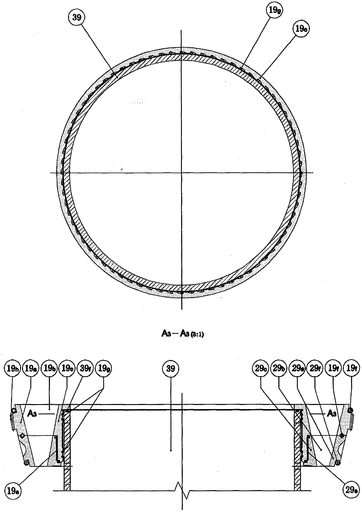
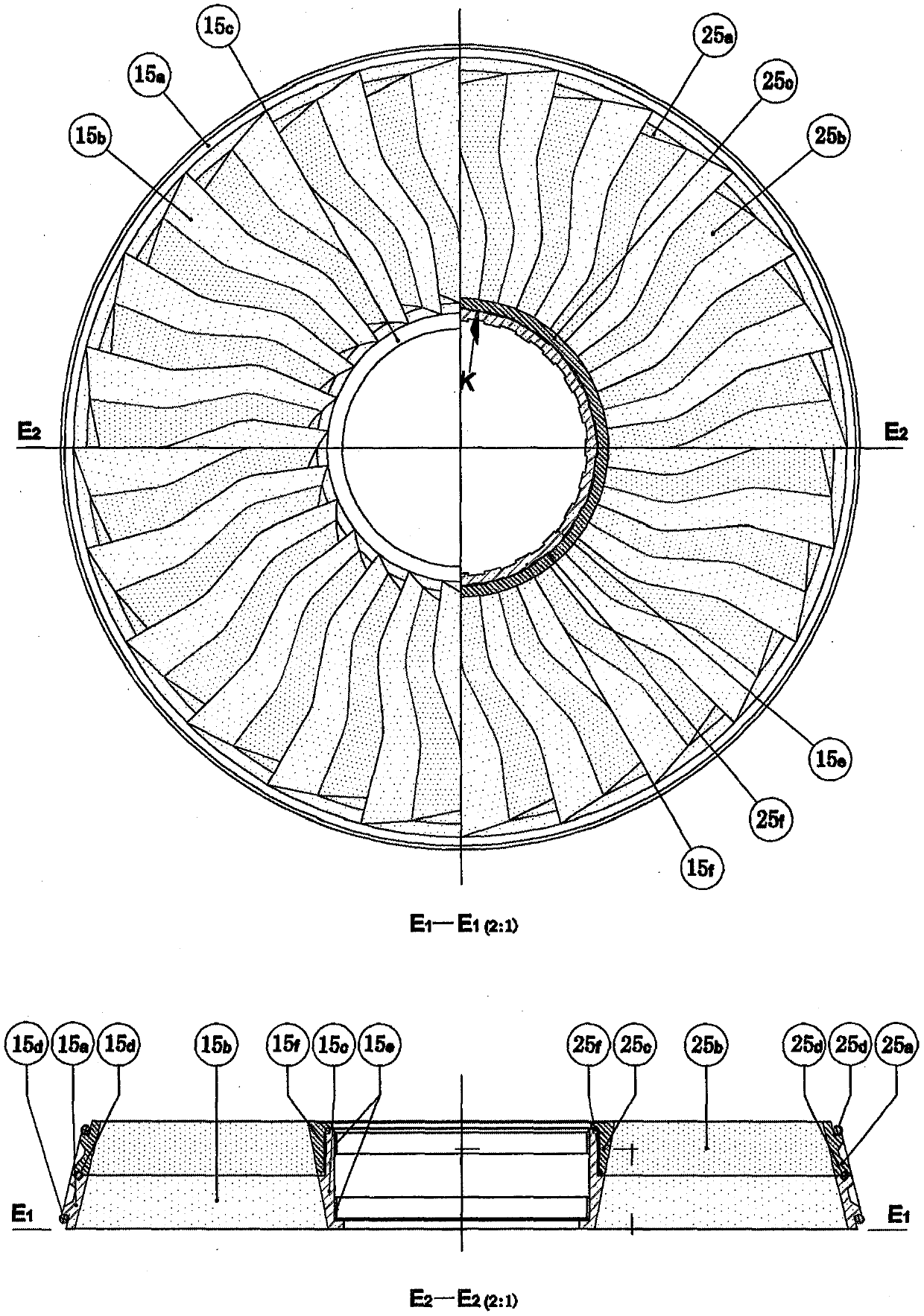
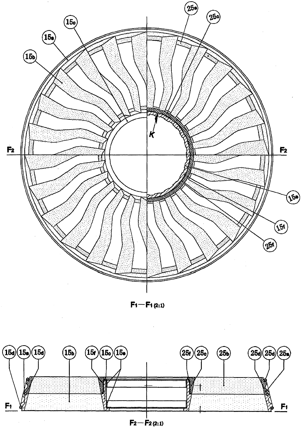
[0018] In order to understand more clearly the technical means adopted by the present invention to the improvement of existing turbojet engine (core machine) in work and transmission mode, structural configuration form, working cooling mode, starting mode, and in order to allow the above-mentioned features of the present invention and The advantages can be more obvious and easy to understand. The following is accompanied by the accompanying drawings, and the detailed description is as follows:

[0019] 1. The multi-shaft sleeve transmission two-way rotating wheel fan turbine and the embedded fan compressor have the following working and transmission modes: a turbine fan drives a corresponding compressor fan to rotate through a transmission sleeve , its working speed and steering are the same and opposite to the rotation direction of the corresponding wheel fan of the adjacent scroll pressure, and the speed of each wheel fan can be different; except for the first wheel fan of th...


PUM


Abstract

The invention discloses a multi-shaft sleeve transmission two-way rotating wheel fan turbine and an inlaid fan compressor, which are composed of a turbine, a compressor wheel fan, a transmission shaft sleeve and other working and transmission components; a support plate, a fixed plate bolt, etc. Structure and installation parts; starting motor and other starting parts. Its working and transmission characteristics are as follows: a turbine wheel fan drives a corresponding compressor wheel fan to rotate through a transmission shaft sleeve, and the rotation direction is opposite to that of the adjacent wheel fan, and the speed is different; the transmission shaft sleeve is divided into multi-layer sets Together, they are inserted into the hubs of the corresponding wheels of the compressor and turbine respectively, and are suspended without additional support bearings; the secondary fans of the compressor are nested on the main fan, and the spokes of the two can be expanded Form one wide chord spoke, or hide behind the main wheel sash to become two narrow chord spokes. The turbojet engine assembled with it has beneficial effects such as high efficiency, light weight, fast heat dissipation, anti-surge, low fuel consumption, and the like.

Description

technical field [0001] The invention relates to a design and improvement in the mechanical field of the structure and structure of the compressor and the fan of the turbojet engine (core machine) for the purpose of improving the working efficiency of the turbojet engine (core engine); thus a multi-shaft sleeve transmission bidirectional Rotating turbofan turbines and nested turbofan compressors. Background technique [0002] The working mode of the air compressor and the turbine of general existing turbojet engine (core machine) is: the multi-stage fan of air compressor rotates and air is compressed to ten times to twenty times and sent into combustion chamber and mixed with fuel, mixed After the gas is ignited in the combustion chamber, it bursts out to the tail of the engine and drives the multi-stage fan of the turbine to rotate. The multi-stage fan of the turbine feeds the rotation of the multi-stage fan of the compressor through a single or multiple transmission shafts ...

Claims


Application Information

Patent Timeline
Patent Type & Authority Patents(China)
IPC IPC(8): F02C3/067
CPCF01D1/20F01D1/26F04D25/024F04D29/321F04D19/005Y02T50/60F02C3/067F01D5/02F01D5/141F01D5/18F02C7/268F02C7/36F04D29/056F04D29/325F04D29/541F05D2260/31
Inventor 苏犁
Owner 苏犁
Why Eureka
Eureka Blog
Learn More