Rotating electric machine

A technology for rotating electrical machines and rotors, applied in the field of rotating electrical machines, can solve the problems of difficult winding operations, deterioration of manufacturability, and lengthening of the stator axis, and achieve the effects of improving the space factor, improving the manufacturability, and shortening the length.

Active Publication Date: 2018-06-08
MITSUBISHI ELECTRIC CORP
View PDF2 Cites 9 Cited by
  • Summary
  • Abstract
  • Description
  • Claims
  • Application Information

AI Technical Summary

Problems solved by technology

[0009] However, in the rotating electric machine described in Patent Document 1, since the coil parts of the same phase on the same circuit are connected to the power supply part side, there is a problem that the length of the stator axial direction of the rotating electric machine becomes long, and winding work is difficult. manufacturing deterioration

Method used


Image

  • Rotating electric machine
  • Rotating electric machine
  • Rotating electric machine

Examples


Embodiment approach 1

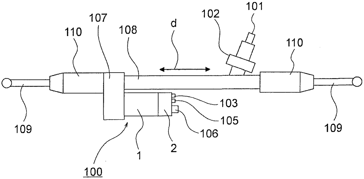
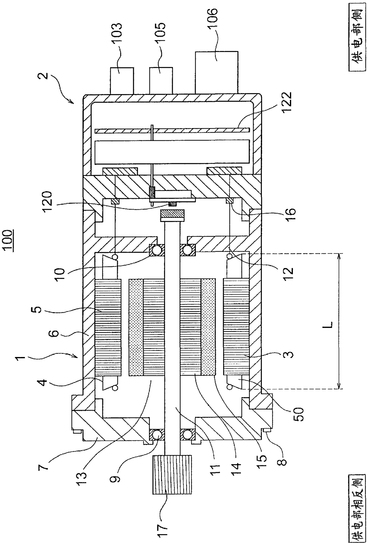
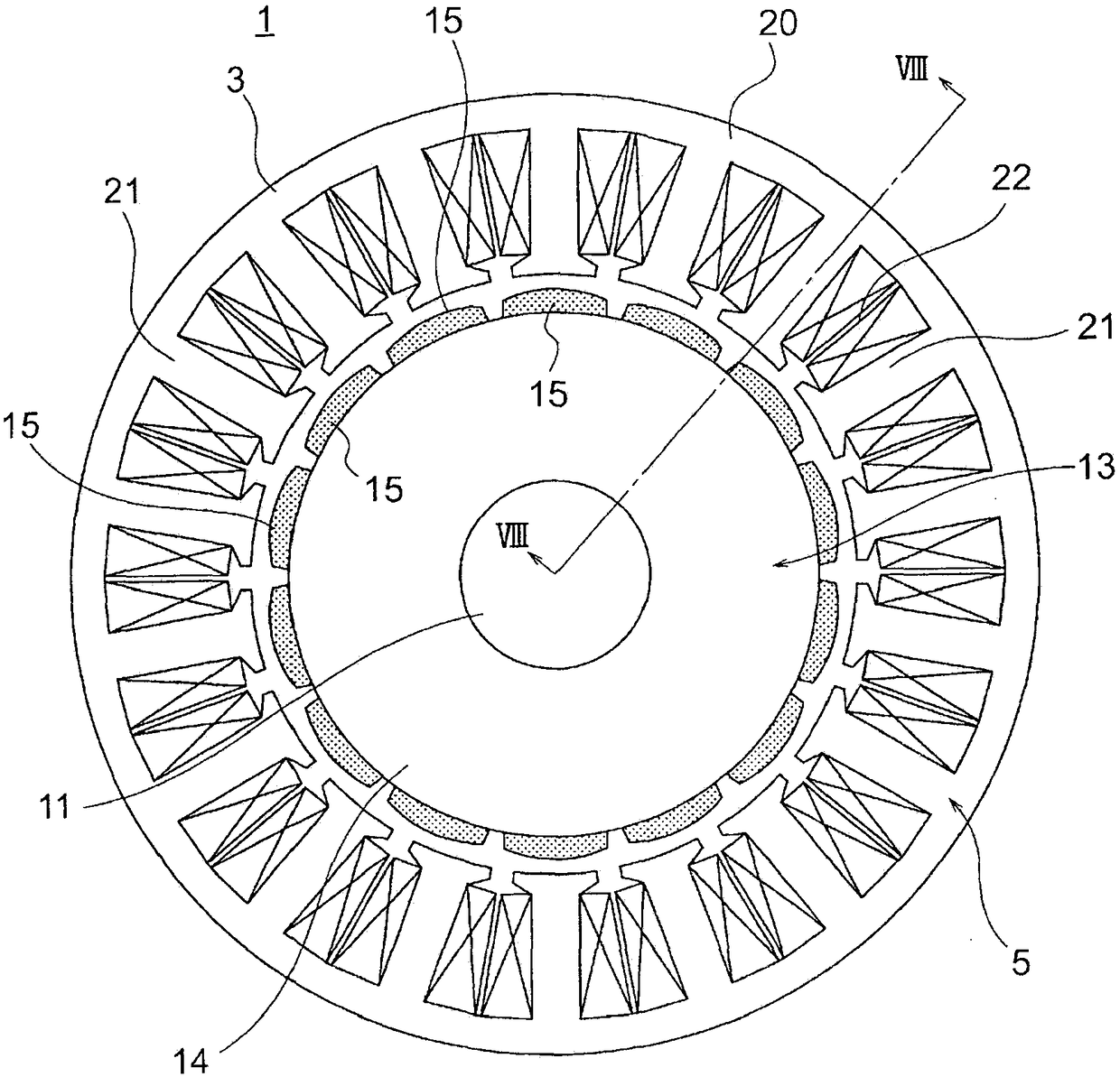
[0049] figure 1 It is a block diagram showing the electric power steering apparatus of the automobile in which the electric motor 1 according to the first embodiment of the present invention is mounted, figure 2 is shown figure 1 The cross-sectional view of the electric drive device 100, image 3 is shown figure 2 The main sectional view of the motor 1, Figure 4 is shown image 3 The main cross-sectional view of the stator 5.

[0050] The electric power steering apparatus includes an electric drive device 100 including an electric motor 1 as a rotating electrical machine, and an ECU 2 (Electric Control Unit) 2 .

[0051] In this electric power steering apparatus, a driver steers a steering wheel (not shown), and the torque thereof is transmitted to the shaft 101 via a steering shaft (not shown). At this time, the torque detected by the torque sensor 102 is converted into an electric signal and transmitted to the ECU 2 via the first connector 103 through a cable (not s...

Embodiment approach 2

[0129] Figure 10 It is a longitudinal cross-sectional view which shows the electric motor 1 which concerns on Embodiment 2 of this invention.

[0130] In this electric motor 1, the number of poles of the rotor 13 is 28, and the number of the teeth 21 of the stator core 3 is 36.

[0131] The rotor 13 is provided with a shaft 11 and a rotor core 14 provided outside the shaft 11 , and 28 permanent magnets 15 are attached to the outer peripheral surface of the rotor core 14 at equal intervals in the circumferential direction.

[0132] Furthermore, although in Figure 10 Although omitted here, in order to protect the permanent magnets 15 and prevent scattering of the permanent magnets 15 , the outer side of the permanent magnets 15 may be covered with a cover made of a non-magnetic material such as stainless steel or aluminum in a cylindrical shape.

[0133] The stator 5 includes a stator core 3 and an armature winding 4 wound around the stator core 3 .

[0134] The stator core...

Embodiment approach 3

[0163] Figure 12 It is a longitudinal cross-sectional view which shows the electric motor 1 which concerns on Embodiment 3 of this invention.

[0164] The number of poles of the rotor 13 of this motor is ten, and the number of the teeth 21 of the stator core 3 is twelve.

[0165] The rotor 13 includes a shaft 11 , a rotor core 14 provided outside the shaft 11 , and ten permanent magnets 15 affixed to the outer peripheral surface of the rotor core 14 at equal intervals in the circumferential direction.

[0166] Furthermore, although in Figure 12 Although omitted here, in order to protect the permanent magnet 15 and prevent the permanent magnet 15 from scattering, the outer side of the permanent magnet 15 may be covered with a cover made of a non-magnetic material such as stainless steel or aluminum in a cylindrical shape.

[0167] The stator 5 includes a stator core 3 and an armature winding 4 wound around the stator core 3 .

[0168] The stator core 3 has an annular core ...


PUM


Abstract

A rotating electric machine is provided with: a rotor having a plurality of magnetic poles; and a stator having a stator core and an armature winding, said stator core having teeth that are provided enclosing the rotor and extend from a core back toward an inner side direction of the rotor, said armature winding being wound around the stator core. The armature winding is constituted by a pluralityof same phase winding portions in which, among coil portions formed by concentratedly winding conducting wires around the respective teeth, same phase coil portions are connected to each other via jumper wires in a series circuit configuration, and which have lead-out wires at both ends thereof. The lead-out wires of the respective same phase winding portions are led out toward one of the axial directions of the rotor from the same phase coil portions disposed adjacent to each other in the circumferential direction of the stator core, and all the jumper wires of the respective same phase winding portions are led out toward the other of the axial directions of the rotor.

Description

technical field [0001] The present invention relates to a rotating electrical machine provided with an armature winding including a plurality of in-phase winding portions in which conductors are concentratedly wound around a plurality of in-phase coil portions of respective teeth via overlapping wires to It is connected in series circuit and has lead wires at both ends. Background technique [0002] There is known a rotating electrical machine including an armature winding having at least two sets of coil portions of the same phase in which wires are wound around teeth of a stator core and arranged adjacent to each other in the circumferential direction and these two adjacent in-phase coil parts in the circumferential direction are connected to the same series circuit to reduce the number of connections. In addition, in order to shorten the overlap wire, the wires are continuously wound around the teeth of other phases, and the phases of the lead wires are connected. Adjace...

Claims


Application Information

Patent Timeline
Patent Type & Authority Applications(China)
IPC IPC(8): H02K3/18H02K3/28
CPCH02K3/18H02K3/28H02K11/33H02K5/225H02K1/2781H02K29/03H02K7/116H02K1/276H02K1/2773H02K2203/06H02K21/16B62D5/0424B62D5/0448H02K1/146H02K1/274H02K3/522
Inventor 池田纮子广谷迪中野正嗣伊藤一将冈崎广大川村浩司
Owner MITSUBISHI ELECTRIC CORP
Why Eureka
Try Eureka