
Amplifier with boosted peaking

A technology of amplifiers and inductors, applied in the field of amplifiers, can solve problems such as signal distortion

Active Publication Date: 2018-06-08
QUALCOMM INC
View PDF10 Cites 4 Cited by
  • Summary
  • Abstract
  • Description
  • Claims
  • Application Information

AI Technical Summary

Problems solved by technology

Frequency-dependent attenuation can cause distortion in signals transmitted across channels, especially in high-frequency signals (e.g., high data rate signals)

Method used


Image

  • Amplifier with boosted peaking
  • Amplifier with boosted peaking
  • Amplifier with boosted peaking

Examples


Embodiment Construction

[0027] The detailed description set forth below with respect to the drawings is intended as a description of various configurations, and is not intended to represent the only configurations in which the concepts described herein can be practiced. The detailed description includes specific details for the purpose of providing a thorough understanding of various concepts. However, it will be obvious to those skilled in the art that these concepts can also be practiced without these specific details. In some cases, well-known structures and components are shown in block diagram form in order to avoid obscuring such concepts.

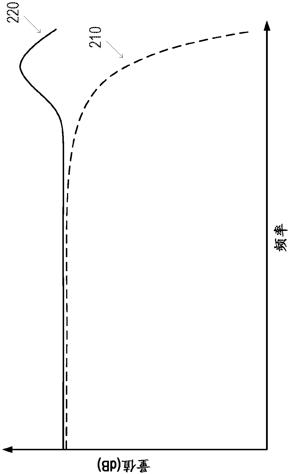
[0028] figure 1 An example of the communication system 110 for transmitting data from the transmitting device 115 to the receiving device 140 through the channel 130 is shown. The communication system 110 may be used in, for example, a serializer / deserializer (SerDes) system to transmit high-speed serial data (for example, 5 Gbit / s or higher) through the cha...


PUM


Abstract

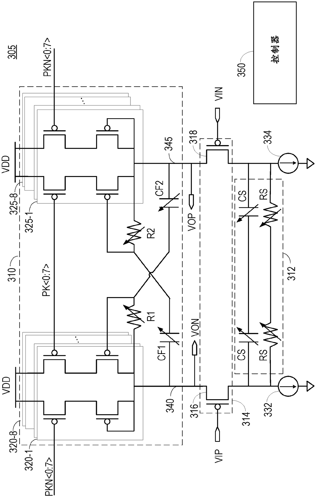
In one implementation, an amplifier (305) comprises a load circuit (310) comprising a plurality of inductor cells, and a drive circuit (314) configured to receive an input signal, and to drive the load circuit (310) based on the input signal to generate an amplified signal. The amplifier (305) also comprises a controller (350) configured to tune a peaking gain of the amplifier (305) by adjusting anumber of the inductor cells that are enabled.

Description

[0001] Cross references to related applications [0002] This application claims the priority and rights of non-provisional application No. 14 / 857,802 filed in the US Patent and Trademark Office on September 17, 2015, the entire contents of which are incorporated herein by reference. Technical field [0003] Aspects of the present disclosure relate generally to amplifiers, and more particularly to amplifiers with improved peaking. Background technique [0004] In a communication system, a signal can be transmitted from a transmitting device to a receiving device across a channel (for example, a cable). The channel can be bandwidth limited, where the channel attenuates the signal at high frequencies. Frequency-dependent attenuation may cause distortion in signals transmitted across the channel, especially in high-frequency signals (eg, high data rate signals). To solve this, the receiving device may include an amplifier (also called an equalizer) with increased peaking at high freq...

Claims


Application Information

Patent Timeline
Patent Type & Authority Applications(China)
IPC IPC(8): H03F3/45H04B3/04H04L25/03H03H11/48
CPCH03F3/45197H03H11/48H04B3/04H04L25/03878H03F2203/45631H03F2203/45644H03F2203/45686H03F2203/45726H04L25/0264H03F3/193H03G3/3036H03F2200/129H03F3/191H03F2200/451H03F2200/372
Inventor 袁晓彬M·普拉萨德J·纳托尼奥
Owner QUALCOMM INC
Learn More