Electric chuck of gear guide rod mechanism

A gear and pinion technology, applied in the field of electric chucks, can solve the problems of high labor intensity and high repeatability, and achieve the effects of reducing labor costs, compact structure and improving work efficiency

Pending Publication Date: 2018-06-12
焦彬彬
View PDF0 Cites 0 Cited by
  • Summary
  • Abstract
  • Description
  • Claims
  • Application Information

AI Technical Summary

Problems solved by technology

[0002] With the continuous improvement and development of industrial technology, the replacement of complex and new labor by automation equipment is the only way for a country to become a powerful country. At present, the existing pipe cutting equipment in the laser cutting industry is still generally placed on the pipe cutting machine manually. And manually manipulate the chuck to clamp the pipe fittings on the chuck, which is labor-intensive and highly repeatable

Method used


Image

  • Electric chuck of gear guide rod mechanism
  • Electric chuck of gear guide rod mechanism
  • Electric chuck of gear guide rod mechanism

Examples


Embodiment Construction

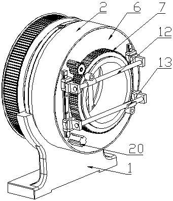
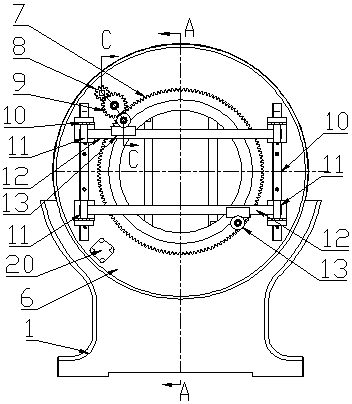
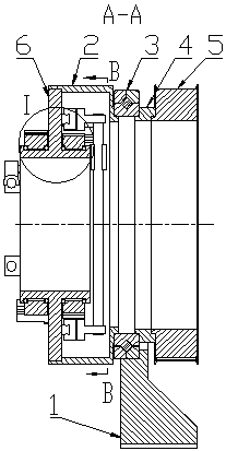
[0008] An electric chuck of a gear guide rod mechanism, which consists of 1 base, 2 rotating discs, 3 cross roller guide rails, 4 connecting discs, 5 synchronous wheels, 6 rotating seats, 7 large gears 1, 8 small gears 1, 9 middle Transmission gear I, 10 linear guide rail I, 11 optical axis seat I, 12 optical axis I, 13 slider I, 14 steel ball I, 15 motor I, 16 intermediate shaft I, 17 bearing, 18 retaining ring for holes, 19 slider Fixed shaft, 20 motor II, 21 small gear II, 22 intermediate transmission gear II, 23 large gear II, 24 slider II, 25 optical axis II, 26 optical axis seat II, 27 linear guide rail II, 28 steel ball II, among which The feature is that: 2 rotating disks are positioned on the inner wall of 3 cross roller guide rails and fixed on the inner wall of 3 cross roller guide rails, the outer wall of 3 cross roller guide rails is fixed in the inner hole of 1 base, 4 one side of the connecting disc is fixed on 3 cross roller guide rails On the inner wall of the...


PUM


Abstract

An electric chuck of a gear guide rod mechanism consists of a base, a rotating disc, a cross roller guide way, a connecting disc, a synchronous wheel, a rotating seat, a main gear I, a pinion gear I,an intermediate transmission gear I, linear guideways I, optical axis seats I, optical axes I, sliding blocks I, steel balls I, a motor I, an intermediate shaft I, bearings, retaining ring for bores,sliding block fixed shafts, a motor II, a pinion gear II, an intermediate transmission gear II, a main gear II, sliding blocks II, optical axes II, optical axis seats II, linear guideways II and steelballs II. The optical axes I and the optical axes II which are perpendicular mutually in the mechanism get close to or far away from the center so as to clamp a steel pipe.

Description

technical field [0001] The invention relates to an electric chuck of a gear guide rod mechanism, which belongs to the field of laser cutting mechanical equipment. Background technique [0002] With the continuous improvement and development of industrial technology, the replacement of complex and new labor by automation equipment is the only way for a country to become a powerful country. At present, the existing pipe cutting equipment in the laser cutting industry is still generally placed on the pipe cutting machine manually. And manually operate the chuck to clamp the pipe fittings on the chuck, which is labor-intensive and highly repeatable. Therefore, there is an urgent need for a chuck device that reduces the repetitive labor of personnel and clamps the pipe fittings in an electric manner. Contents of the invention [0003] In view of the above disadvantages, the present invention provides an electric chuck of a gear guide rod mechanism. [0004] The present invent...

Claims


Application Information

Patent Timeline
Patent Type & Authority Applications(China)
IPC IPC(8): B23K37/053B23K26/38B23K101/06
CPCB23K37/0533B23K26/38
Inventor 焦彬彬
Owner 焦彬彬
Why Eureka
Try Eureka