
Active anti-roll bar and control method thereof

A technology of a stabilizer bar and a control method, which is applied in interconnection systems, vehicle springs, vehicle components, etc., can solve the problems of vehicle driving safety, stiffness cannot be adjusted, and roll angle stiffness cannot be adjusted, so as to meet the softness of the suspension Comfort requirements, good suspension soft comfort requirements, the effect of meeting the anti-rolling safety requirements

Active Publication Date: 2018-06-12
JILIN UNIV
View PDF9 Cites 12 Cited by
  • Summary
  • Abstract
  • Description
  • Claims
  • Application Information

AI Technical Summary

Problems solved by technology

[0003] The traditional anti-roll bar is fixed in a single form, and the stiffness cannot be adjusted. It cannot reasonably adjust the roll angle stiffness according to the driving state of the vehicle, and it cannot take into account the anti-roll requirements of high-speed good road driving and the comfort and passability of low-speed bumpy road driving. Require
[0004] The existing active anti-roll bar is mainly divided into hydraulic type and electric motor type. The hydraulic type active anti-roll bar has a complicated structure and slow corresponding speed, which is difficult to meet the needs of changing working conditions. The reliability is not high, and oil leakage will cause pollution. environment, and due to the change of oil viscosity, the effect of low temperature use in winter is poor
In addition, compared with the hydraulic type, the motor-type active anti-roll bar developed by ZF has a relatively simple actuator and is easy to control. However, due to the use of a single motor structure, although it can change the torsional stiffness of the anti-roll bar steplessly, it still cannot Realize the decoupling control of the left and right suspension of the vehicle, resulting in partial loss of ride comfort
In addition, the left and right suspension independent active anti-roll technology used by Audi can solve the problem of decoupling the travel control of the left and right suspensions, but because it requires two independent motors, the cost is high, the space is large, and the reliability is poor. When the tilting motor fails, there will be an unsafe driving feeling that the performance of one side of the roll is significantly different from that of the other side, and the ideal anti-rolling effect cannot continue to be achieved, which may cause car driving safety problems

Method used


Image

  • Active anti-roll bar and control method thereof
  • Active anti-roll bar and control method thereof
  • Active anti-roll bar and control method thereof

Examples


Embodiment Construction

[0057] The present invention will be further described in detail below in conjunction with the accompanying drawings, so that those skilled in the art can implement it with reference to the description.

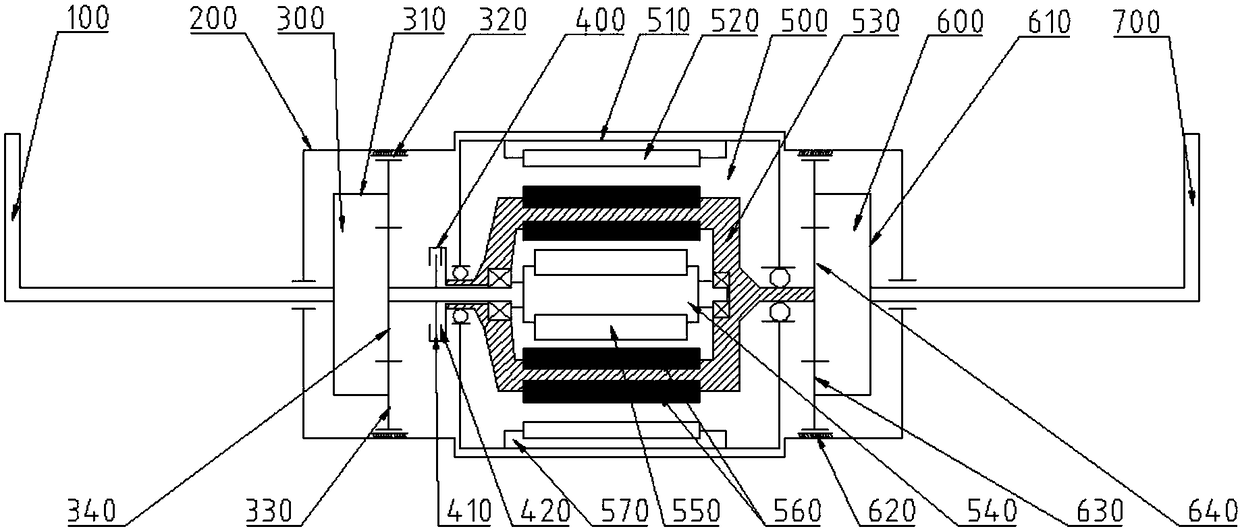
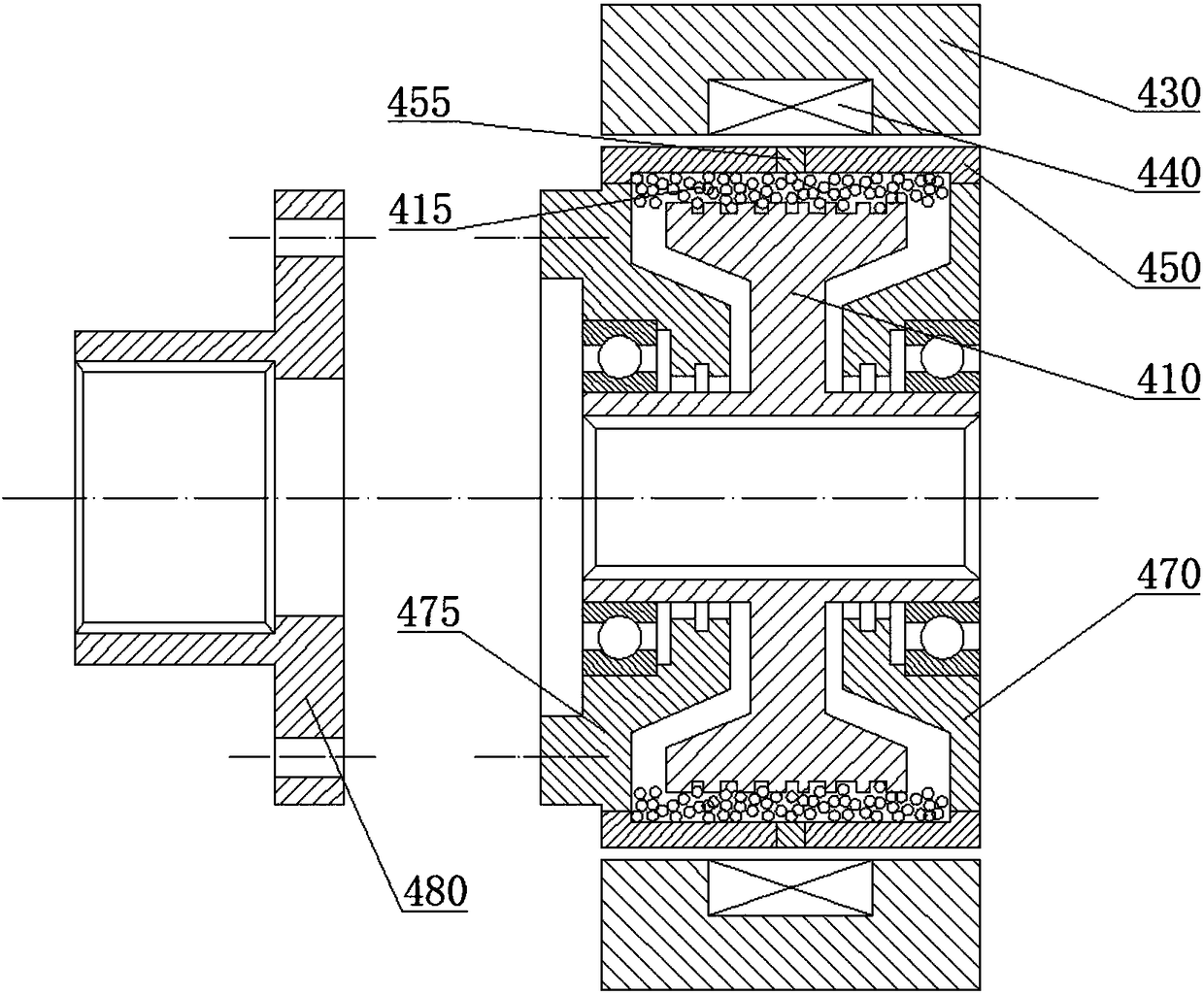
[0058] Such as figure 1 As shown, an active anti-roll bar according to the present invention includes a left half anti-roll bar 100, an actuator casing 200, a left planetary gear mechanism 300, a magnetic powder clutch 400, a flange 480, a double-rotor motor 500, and a right planetary gear Mechanism 600, right anti-roll half rod 700.

[0059] Such as figure 1 As shown, the left anti-roll half rod 100 has an L-shaped structure, and the material is spring steel or other alloy materials. The outer end of the left anti-roll half rod is connected with the lower guide arm of the left suspension through a ball stud, or connected The rod is connected to the lower end of the left shock absorber, the inner end of the left anti-roll half rod is splined to the center hole of the left p...


PUM


Abstract

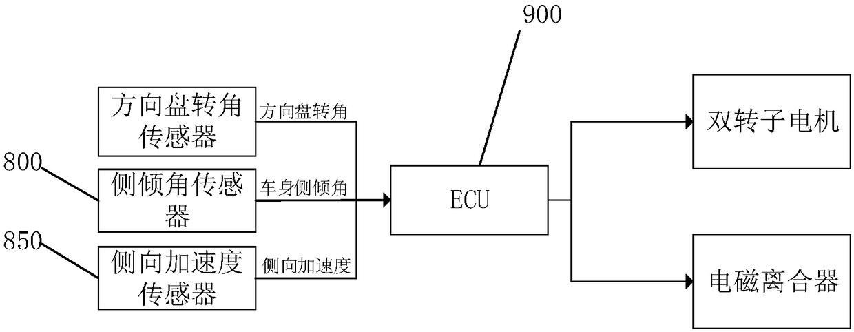
The invention discloses an active anti-roll bar. The anti-roll bar comprises a left half anti-roll bar, a right half anti-roll bar, a left planetary gear set, a right planetary gear set, a magnetic powder clutch, a double-rotor motor and an ECU and is characterized in that the magnetic powder clutch comprises a drive end and a driven end, and the magnetic powder clutch selectively combines or separates the drive end and the driven end; the double-rotor motor comprises an inner rotor and an outer rotor, the inner rotor is connected to the drive end of the magnetic powder clutch and penetrates the magnetic powder clutch to be connected with the sun gear of the left planetary gear set, the leading-out end of the outer rotor is connected with the driven end of the magnetic powder clutch through a flange and a bolt, and the other output end of the outer rotor is connected with the sun gear of the right planetary gear set; the ECU is electrically connected with the double-rotor motor and themagnetic powder clutch. The active anti-roll bar has the advantages that suspension roll angle rigidity can be changed actively and steplessly, whole-vehicle high-speed roll stability, whole-vehiclelow-speed suspension comfortableness and a system failure protecting function are also achieved, independent travel control of a left suspension and a right suspension can be achieved, active roll canbe achieved, and vehicle body lateral collision passive safety is increased.

Description

technical field [0001] The invention relates to the technical field of automobiles, in particular to an active lateral stabilizer bar and a control method thereof. Background technique [0002] The anti-roll bar of the car is also called the lateral stabilizer bar. Its purpose is that when the car is turning or driving on a bumpy road, the jump of the suspension on both sides of the vehicle is different, so that the anti-roll bar will be torsionally deformed to produce a reverse anti-torsion effect. The moment restrains the body roll, and the anti-roll bar can effectively reduce the roll angle of the independent suspension vehicle when turning, and improve the vehicle's handling stability. [0003] The traditional anti-roll bar is fixed in a single form, and the stiffness cannot be adjusted. It cannot reasonably adjust the roll angle stiffness according to the driving state of the vehicle, and it cannot take into account the anti-roll requirements of high-speed good road dri...

Claims


Application Information

Patent Timeline
Patent Type & Authority Applications(China)
IPC IPC(8): B60G21/055
CPCB60G21/0553B60G2202/135B60G2202/42
Inventor 王军年罗正
Owner JILIN UNIV
Learn More