Aircraft electronic brake system and braking method using automatic brake switch
A technology of automatic braking and braking system, which is applied in the direction of aircraft braking arrangement, braking transmission device, brake, etc., can solve the problems of difficulty in troubleshooting and positioning, low reliability of use, potential safety hazards, etc., and improve the utilization of airport runways. efficiency and equipment utilization, high reliability, flexible and convenient use
- Summary
- Abstract
- Description
- Claims
- Application Information
AI Technical Summary
Problems solved by technology
Method used
Image
Examples
Embodiment 1
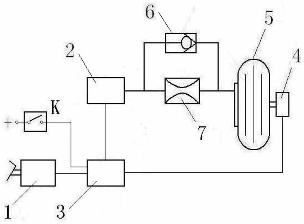
[0035] see figure 1 . The front landing gear wheels of modern aircraft generally do not have brakes, and brake devices are equipped on the wheels of the two main landing gears. The two aircraft main landing gears are usually arranged symmetrically on both sides of the aircraft fuselage. In this embodiment, one of the main landing gear and one wheel is installed as an example to illustrate an aircraft fly-by-wire hydraulic braking system with automatic braking capability.
[0036] This embodiment is a first-level automatic brake; the automatic brake anti-skid valve adopts a shared anti-skid valve, and an electro-hydraulic servo valve is used as the anti-skid valve.
[0037] In this embodiment, the braking command sensor 1, the control box 3, the electro-hydraulic servo valve 2 and the speed sensor 4 form a conventional braking system. The control box 3, the electro-hydraulic servo valve 2 and the speed sensor 4 form a conventional anti-skid control system.
[0038] This emb...
Embodiment 2
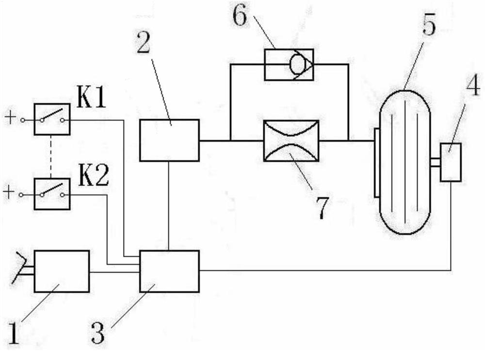
[0062] see figure 2 . This embodiment is an aircraft fly-by-wire hydraulic braking system with automatic braking capability. The difference from the technical solution in Embodiment 1 is that the aircraft fly-by-wire hydraulic braking system of this embodiment is a two-stage automatic braking system.
[0063]This embodiment includes a brake command sensor 1 , a control box 3 , an electro-hydraulic servo valve 2 , a first automatic brake switch K1 , a second automatic brake switch K2 , a throttle 7 , a one-way valve 6 and a speed sensor 4 . The brake command sensor 1, the control box 3, the electro-hydraulic servo valve 2 and the speed sensor 4 form a conventional brake system. The control box 3, the electro-hydraulic servo valve 2 and the speed sensor 4 form a conventional anti-skid control system. Automatic brake switch K, electro-hydraulic servo valve 2, throttle 7, check valve 6, speed sensor 4 and control box 3 form an automatic brake system. Electro-hydraulic servo va...
PUM
 Abstract
Description
Claims
Application Information
 - R&D
- Intellectual Property
- Life Sciences
- Materials
- Tech Scout
- Unparalleled Data Quality
- Higher Quality Content
- 60% Fewer Hallucinations
Browse by: Latest US Patents, China's latest patents, Technical Efficacy Thesaurus, Application Domain, Technology Topic, Popular Technical Reports.
© 2025 PatSnap. All rights reserved.Legal|Privacy policy|Modern Slavery Act Transparency Statement|Sitemap|About US| Contact US: help@patsnap.com


