Radiant annealing method for camera bracket

A camera and bright annealing technology, applied in furnaces, furnace types, heat treatment equipment, etc., can solve the problems of reduced work efficiency, internal impact of the furnace body, large air flow, etc., and achieve short working time, reduced impact, and small air flow Effect

Active Publication Date: 2019-04-02
李倩楠
View PDF5 Cites 0 Cited by
  • Summary
  • Abstract
  • Description
  • Claims
  • Application Information

AI Technical Summary

Problems solved by technology

[0004] Due to the large volume of the vacuum furnace used, it takes a long time to evacuate the vacuum furnace, which will lead to a decrease in work efficiency
In addition, when the workpiece is cooled and the furnace body is in a vacuum state, it is not convenient to open the furnace door; in order to make it easier to open the furnace door, a pressure relief valve is usually installed to allow air to slowly enter the furnace body through the pressure relief valve, and then Open the oven door, but it will take a long time
If the furnace door is opened when the furnace body is still in a vacuum state, the air will rush into the furnace body quickly, and because of the large space in the furnace body, the air flow into the furnace body is relatively large, so that when the air enters the furnace body, it will With a large impact, it is easy to damage the heat source

Method used


Image

  • Radiant annealing method for camera bracket
  • Radiant annealing method for camera bracket

Examples


Embodiment 1

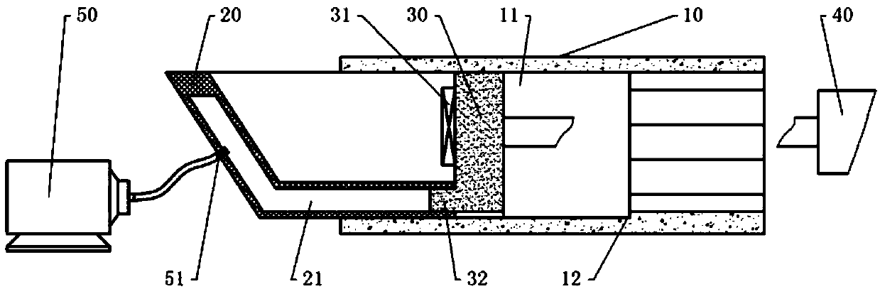
[0031] The method for bright annealing of the camera bracket in this embodiment uses a vacuum annealing furnace to perform bright annealing on the bracket. Such as figure 1As shown, the vacuum annealing furnace includes a furnace body 10, a feeding part and a traction part, and the feeding part and the traction part are arranged from left to right. The furnace body 10 is provided with a heating chamber 11 with openings at both ends. The feeding part includes a feeding tank 20 and a vacuum pump 50 , and the feeding tank 20 is arranged in the heating chamber 11 and is slidably connected with the furnace body 10 . The top and the right side opening of feed chute 20, when push feed chute 20 to the left, make the part of feed trough 20 slide out from heating cavity 11, then can pass the opening of feed chute 20 tops to feed chute 20 Insert the workpiece inside. A vacuum chamber 21 is provided in the side wall of the feed tank 20 , and a first notch is provided on the right side o...

Embodiment 2

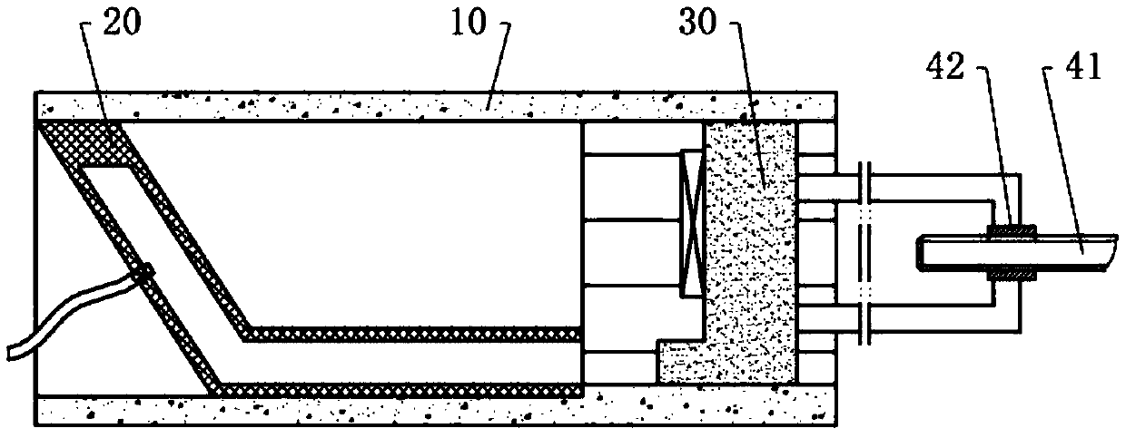
[0043] Such as figure 2 As shown, the difference between the second embodiment and the first embodiment is only that the traction mechanism in the second embodiment includes a servo motor, a lead screw 41 and a nut 42 matched with the lead screw 41, and the lead screw 41 passes through the output of the flange plate and the servo motor. The shaft is fixedly connected, and the nut 42 is fixed on the right side of the blocking block 30, so the blocking block 30 can be driven to slide left and right in the heating box through the forward and reverse rotation of the servo motor.


PUM


Abstract

The invention relates to the technical field of camera machining and particularly discloses a bright annealing method of a camera support. The bright annealing method of the camera support comprises the steps that (1) vacuumizing treatment is conducted on a vacuum cavity, a feeding groove is pushed out by a drawing mechanism from an opening at the left end of the heating cavity, and workpieces arefed into the feeding groove from a top opening of the feeding groove; (2) a plug block is pulled by the drawing mechanism to slide in the heating cavity, the plug block is pulled to the right end ofa furnace body, and after a vacuum pump stops work, a heater is connected with a power source; (3) the temperature of the heating cavity is raised to 410-450 DEG C, and the temperature is kept for 5-6hours; (4) after the temperature of the heating cavity is raised to 600-650 DEG C and kept for 1-1.5 hours, the heater is switched off; (5) after the temperature in the heating cavity is lowered to below 50 DEG C, the feeding groove is pushed out from the opening at the left end of the heating cavity, and the workpieces are taken out from the feeding groove. By the adoption of the bright annealing method of the camera support, a device can rapidly conduct vacuumizing on the heating cavity, and it is avoided that when the heating cavity is opened, air flushes into the heating cavity and damages the heater.

Description

technical field [0001] The invention relates to the technical field of camera processing, in particular to a method for glow annealing of a camera bracket. Background technique [0002] Present camera bracket is generally steel structure, and its interior is provided with the cavity that is used for threading; In order to prevent the bracket from rusting and corroding, paint can be sprayed on the surface of the bracket to prevent the surface of the bracket from being exposed to the air. Since most of the cameras of the monitoring system will be installed outdoors, the paint on the surface of the bracket will soon fall off from the surface of the bracket under the action of wind and sand. If the bracket is exposed to the air and washed by rain for a long time, the bracket will be corroded quickly, which will lead to the exposure of the cable and eventually lead to the aging of the cable. In order to improve the corrosion performance of the stent, currently the stent is usual...

Claims


Application Information

Patent Timeline
Patent Type & Authority Patents(China)
IPC IPC(8): C21D1/26C21D1/773C21D9/00
CPCC21D1/26C21D1/773C21D9/0068
Inventor 冯仁海
Owner 李倩楠
Why Eureka
Try Eureka