Door machine integrated dam

A technology of integrating dam and gate machine, applied in the field of flip gate, can solve the problems of large size of middle pier, affecting flood flow, corrosion and insulation of electric control device, etc.

Active Publication Date: 2021-04-23
THE JIANGSU GENERAL FACTORY OF WATER CONSERVANCY MACHINERY
View PDF8 Cites 2 Cited by
  • Summary
  • Abstract
  • Description
  • Claims
  • Application Information

AI Technical Summary

Problems solved by technology

Its disadvantages are: 1. In order to ensure that the hoist can drive the entire door to rotate from both ends, it is necessary to set a relatively strong bottom shaft tube, and the bottom shaft tube must be integrated, especially for wider rivers. The increase in the size of the shaft tube leads to a sharp increase in cost. The bottom shaft tube needs to form a movable couple with the hinge seat, and its anti-corrosion requirements, strength requirements, and coaxiality requirements are relatively high, which is equivalent to large-sized finishing parts. , its cost is about 40% of the overall steel dam gate
2. Since the door body is driven to rotate from both ends or one end, the hoist needs to be set larger, and the crank arm also needs to be set larger. The hoist itself is a kind of oil cylinder, which needs to be set in the hoist room. Therefore, the setting of the hoist room will also cause the cost to rise
3. Since the pressure of the water from the upstream is also very huge, it is often necessary to set up multiple middle piers in the river channel to install the hinge seats supporting the bottom shaft pipe, and the size of the middle piers is correspondingly relatively large, so that Setting can seriously affect flooding
4. Due to the installation of the bottom shaft tube through the wall, it is difficult to seal the bottom shaft tube and the hoist room, and often due to water leakage from the river to the hoist room, the hoist, electric control device is corroded and the insulation fails, etc.

Method used


Image

  • Door machine integrated dam
  • Door machine integrated dam
  • Door machine integrated dam

Examples


Embodiment Construction

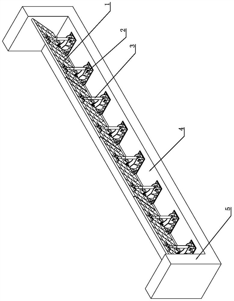
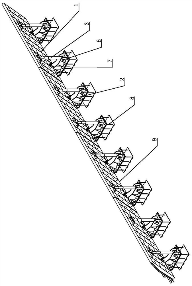
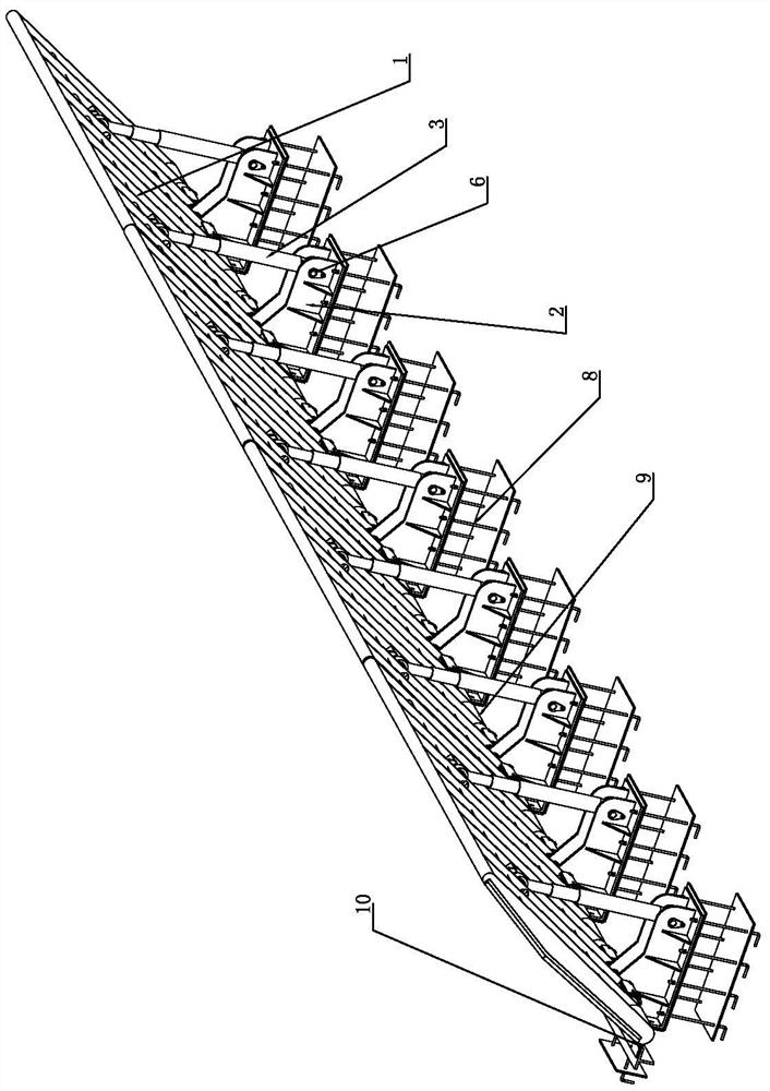
[0024] As shown in the figure, it is a gate machine integrated dam, including a gate body 1 installed between the gate walls 5. The left and right sides of the gate body 1 form a sealing structure with the gate wall 5 by installing side water-stop rubber to prevent side water leakage. A bottom waterproof rubber 10 is installed between the bottom of the door body 1 and the bottom sill 4 to form a sealed structure to prevent water leakage at the bottom. Several hinge seats 2 are fixed on the bottom sill 4; The front pin shaft 7 is hingedly connected, and the backwater side of the door body 1 is provided with a hydraulic cylinder 3. The hydraulic cylinder 3 is a secondary oil cylinder. The rear pin 6 is hingedly connected to the rear end of the hinge seat 2 through the rear. The hinge seat 2 is fixedly installed on the sill embedded part 8 by bolts, the sill 4 is provided with an L-shaped step, and the sill embedded part 8 is embedded on two mutually perpendicular surfaces of the...


PUM


Abstract

The invention discloses a gate machine integrated dam in the field of hydraulic facilities, which includes a gate body installed between gate walls, and the left and right sides of the gate body form a sealing structure by installing side water-stop rubbers and gate walls to prevent side water leakage. A bottom water-stop rubber is installed between the bottom of the door body and the bottom sill to form a sealed structure to prevent water leakage at the bottom. Several hinge seats are fixed on the bottom sill; the bottom of the door body and the front end of the hinge seat are hinged through the front pin. A hydraulic cylinder is arranged on the back side of the body, one end of the hydraulic cylinder is hinged to the back of the door body through the upper pin, and the other end of the hydraulic cylinder is hinged to the rear end of the hinge seat through the rear pin. The device has the advantages of low cost, simple control and convenient management, can be used in various river courses, especially in wide river courses, and has high cost performance.

Description

technical field [0001] The invention relates to a hydraulic facility, in particular to a flip gate. Background technique [0002] In recent years, with the development of social economy and the acceleration of urban modernization, new requirements and contents have been put forward for the construction of urban water conservancy projects. In addition to meeting the requirements of flood control safety, they also need to meet the requirements of improving and beautifying the environment, thus requiring water conservancy projects Gradually realize the transformation from traditional engineering water conservancy to resource water conservancy and ecological water conservancy, pay attention to the landscape and aesthetic requirements of water conservancy projects, and seek new ideas for urban landscape water conservancy planning and design. Because the traditional gate layout requires thick gate piers and protruding hoist bents, which affect the flood control capability and land...

Claims


Application Information

Patent Timeline
Patent Type & Authority Patents(China)
IPC IPC(8): E02B7/40E02B7/44E02B7/54E02B7/00
CPCE02B7/00E02B7/40E02B7/44E02B7/54
Inventor 张立明陆伟刚王勇顾永明高新
Owner THE JIANGSU GENERAL FACTORY OF WATER CONSERVANCY MACHINERY
Why Eureka
Try Eureka