
Continuous wall formwork and construction method of continuous wall

A wall formwork and formwork technology, which is applied to sheet pile walls, infrastructure engineering, construction, etc., can solve the problems of uneven concrete, easy generation of voids, easy to shake, etc., and achieves simple construction technology, guaranteed stability, and simple structure. Effect

Active Publication Date: 2018-06-12
GUANGZHOU ENG CO LTD OF CHINA RAILWAY 19TH BUREAU GRP
View PDF7 Cites 0 Cited by
  • Summary
  • Abstract
  • Description
  • Claims
  • Application Information

AI Technical Summary

Problems solved by technology

[0003] However, during the construction of the existing underground diaphragm wall, the reinforcement cage needs to be bound, and the structure of the reinforcement cage is complicated, which increases the construction workload.
In addition, the hoisted reinforcement cage cannot form a stable connection with the bottom of the deep groove, resulting in poor stability and firmness of the reinforcement cage during the construction of the diaphragm wall, which is prone to shaking
Furthermore, when pouring concrete to the reinforcement cage, the concrete is injected into it through one or several conduits, so that the injection of concrete is likely to be uneven, the concrete injection of each part is not synchronized, and it is easy to generate voids, reducing the continuous underground. wall quality

Method used


Image

  • Continuous wall formwork and construction method of continuous wall
  • Continuous wall formwork and construction method of continuous wall
  • Continuous wall formwork and construction method of continuous wall

Examples


no. 2 example

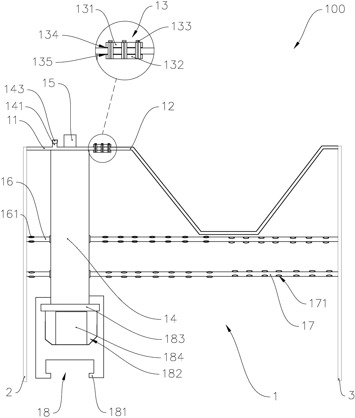
[0043] Such as Figure 4 As shown, applying the inventive concept of the first embodiment of the continuous wall formwork, the difference between the second embodiment of the continuous wall formwork and the first embodiment is that the formwork assembly of the second embodiment includes a plurality of formwork units 60, and one formwork unit The second end of the second steel frame plate 62 of 60 is connected with the second end of the first steel frame plate 61 of another formwork unit 60 by connector 63; The second end of the first connecting pipe 64 of another template unit 60 is connected.

[0044] The first end face formwork 7 is fixedly connected to the second end of the first steel frame plate 61 of the formwork unit 60 at the head end of the formwork assembly, and the second end of the first connecting pipe 64 of the formwork unit 60 at the head end of the formwork assembly is sealed. . The second end formwork 8 is fixedly connected to the second end of the second s...


PUM


Abstract

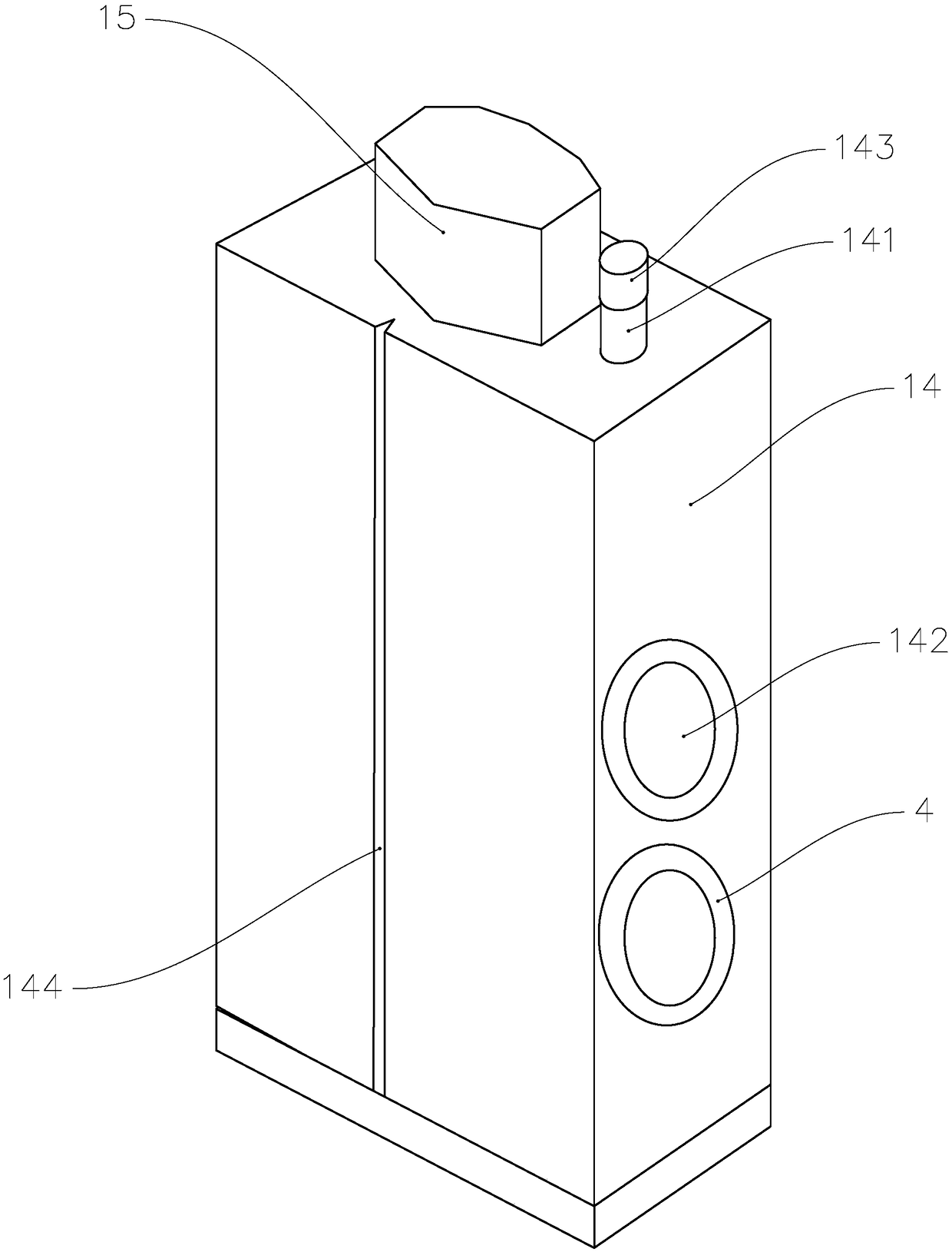
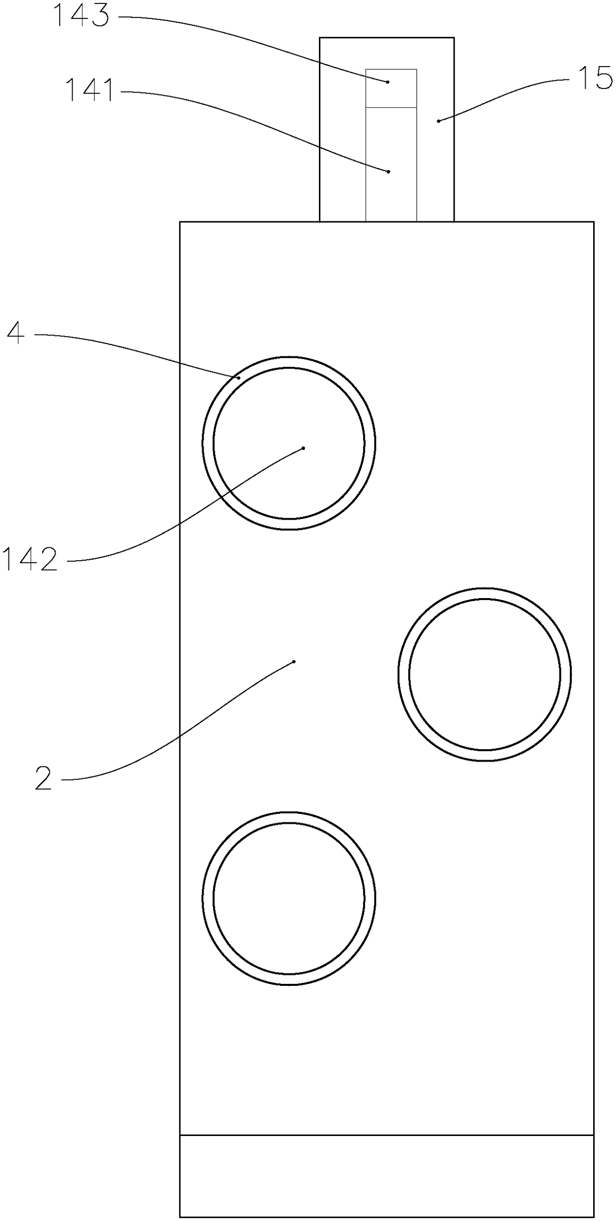
The invention provides a continuous wall formwork and a construction method of a continuous wall. The continuous wall formwork comprises a formwork assembly, a first end face formwork and a second endface formwork. The formwork assembly comprises a formwork unit with a first steel frame plate, a second steel frame plate, a wall column, a balancing part, a first grouting branched pipe, a second grouting branched pipe and a fixing base. The wall column and the balancing part are installed at the two sides of the first steel frame plate correspondingly, and the wall column is provided with a first connector connected with the first grouting branched pipe, a second connector connected with the second grouting branched pipe and a grouting opening. The first grouting branched pipe and the second grouting branched pipe are provided with a first grout outlet hole and a second grout outlet hole separately. The first end face formwork and the second end face formwork are fixedly connected withthe two ends of the formwork assembly correspondingly. The wall column is fixedly installed on the fixing base. The continuous wall construction method used for conducting continuous wall constructionthrough the continuous wall formwork is further provided. The continuous wall formwork has the advantages of being good in firmness and high in stability. The construction method has the advantages that the construction technology is easy and construction is convenient.

Description

technical field [0001] The invention relates to the technical field of continuous wall construction, in particular to a formwork for a continuous wall and a construction method for a continuous wall using the formwork for the continuous wall. Background technique [0002] The underground diaphragm wall project is a basic project, and its main function is to pour out a wall to play the functions of water interception, seepage prevention, load bearing, water retention, etc., and then protect the buildings located inside the wall. The underground diaphragm wall at the pouring place can be applied to pump stations, pools, building foundation pits, underground oil depots and warehouses, etc.; it is also used for shafts of municipal pipe trenches and culvert shields; in addition, diaphragm walls can also be used as various deep foundations And anti-seepage walls of pile foundations, wharves, revetment, dry dock water conservancy and hydropower, open-pit mines, tailings dams and en...

Claims


Application Information

Patent Timeline
Patent Type & Authority Applications(China)
IPC IPC(8): E02D5/18
CPCE02D5/187Y02E10/20
Inventor 陈冬冬王胤赵勇邱久波刘涛
Owner GUANGZHOU ENG CO LTD OF CHINA RAILWAY 19TH BUREAU GRP
Learn More