Underground comprehensive pipe gallery prefabricated assembling construction method

A technology of prefabricated assembly and construction method, applied in artificial islands, water conservancy projects, underwater structures, etc., can solve the problems of low construction efficiency, damage to the pipe gallery structure, large size error, etc., to improve construction efficiency and quality, save money Construction cost and the effect of improving construction efficiency

Inactive Publication Date: 2018-06-12
中铁十一局集团第五工程有限公司
View PDF3 Cites 11 Cited by
  • Summary
  • Abstract
  • Description
  • Claims
  • Application Information

AI Technical Summary

Problems solved by technology

[0004] (1) During the binding and forming process of the steel cage, the dimensional error is large, which cannot ensure that the steel cage can be put into the mold smoothly at one time; (2) When hoisting, it is necessary to place a ceiling on the pipe gallery, and when loading the installation bracket, it is necessary to screw in the pipe gallery, which will damage the steel cage. The structure of the pipe gallery causes water seepage; (3) The assembly position of the pipe gallery is a weak ring, which cannot effectively prevent the impact of ground subsidence on the pipe gallery; (4) The construction efficiency is low, and the construction quality and progress need to be improved
Therefore, the prefabricated assembly construction of underground pipe gallery is currently in the exploratory stage, and there is no scientific and reasonable comprehensive construction method yet.

Method used

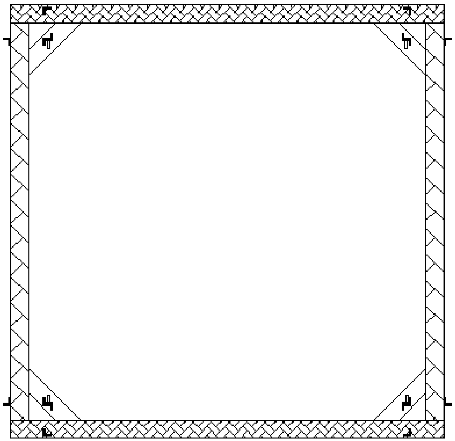
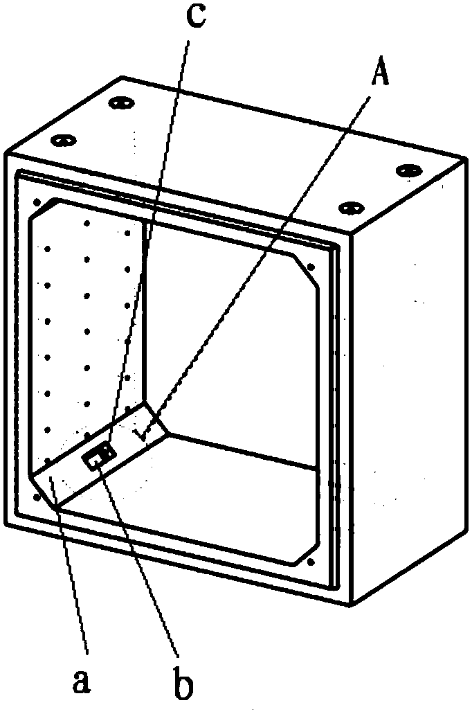
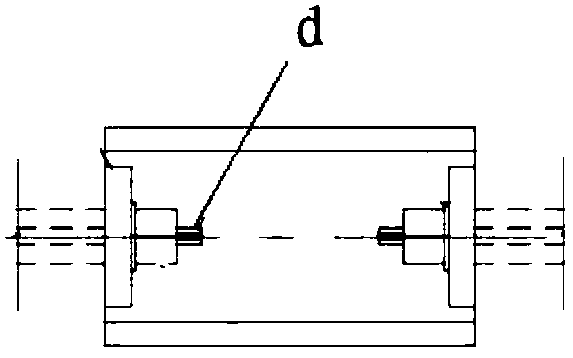

Image

  • Underground comprehensive pipe gallery prefabricated assembling construction method
  • Underground comprehensive pipe gallery prefabricated assembling construction method
  • Underground comprehensive pipe gallery prefabricated assembling construction method

Examples


Embodiment Construction

[0025] Below by embodiment and in conjunction with accompanying drawing, the present invention will be further described:

[0026] A prefabricated and assembled construction method for an underground comprehensive pipe gallery, comprising the following steps:

[0027] (1) Make molds and reinforcement cages;

[0028] (2) Concrete pouring and vibration;

[0029] (3) Steam curing and demoulding;

[0030] (4) lifting and transportation;

[0031] (5) Assembly. The above steps are the necessary steps of the prefabricated assembly construction method of the underground comprehensive pipe gallery, and the key of the present invention is:

[0032] Before step (1), carry out BIM modeling, simulate the pre-construction of the entire project, conduct collision checks in various disciplines, optimize construction drawings in a timely manner, realize refined management and dynamic management of project costs, and significantly improve construction efficiency and save construction costs...


PUM


Abstract

The invention discloses an underground comprehensive pipe gallery prefabricated assembling construction method. The underground comprehensive pipe gallery prefabricated assembling construction methodcomprises the following steps that (1), a mold and a reinforcement cage are prepared; (2) concrete is poured and vibrated; (3), steam curing and demoulding are carried out, (4), lifting and transportation are carried out; and (5), assembling is carried out. A BIM modeling is carried out before the step (1) is carried out; reinforcing steel bar cage construction is formed by auxiliary binding andbinding of a reinforcing steel bar shaping tire film; after the reinforcing steel bar cage is put into a mold, a hanging nail and a bolt are pre-buried; after concrete pouring is completed, an auxiliary angle at the corner position of the inner wall of a prefabricated pipe gallery is carried out, and a tensioning groove is formed in the middle of the auxiliary angle; and a first section of the prefabricated pipe gallery is spliced from the lowest gradient, and when two sections of two pipe gallery are assembled, a jack is combined to carry out opposite angle tensioning until the four corner parts are tensioned and pulled. The reinforcement cage can be smoothly fed into a die once, the pipe gallery structure does not need to be punctured in the pipe gallery when a support is hoisted and installed, the influence of ground settlement on the pipe gallery can be effectively prevented, and the construction efficiency and the construction quality are improved.

Description

technical field [0001] The invention relates to the technical field of pipe galleries for urban underground pipe network systems, in particular to a prefabrication and assembly construction method for underground comprehensive pipe galleries. Background technique [0002] Compared with the cast-in-place pipe gallery, the prefabricated pipe gallery has good appearance quality, high construction efficiency, less environmental pollution and less material waste. The existing prefabricated assembly construction method of the pipe gallery mainly includes several steps of making molds and steel cages, concrete pouring and vibration, steam curing, lifting and transportation, and assembly. [0003] The main problems of this construction method are: [0004] (1) During the binding and forming process of the steel cage, the dimensional error is large, which cannot ensure that the steel cage can be put into the mold smoothly at one time; (2) When hoisting, it is necessary to place a ce...

Claims


Application Information

Patent Timeline
Patent Type & Authority Applications(China)
IPC IPC(8): E02D29/045
CPCE02D29/045E02D29/10
Inventor 谭欣王元清史继元邹学利姜志方兵
Owner 中铁十一局集团第五工程有限公司
Why Eureka
Try Eureka