Axial plunger type hydraulic pump

A plunger type, hydraulic pump technology, applied in variable capacity pump components, pumps, multi-cylinder pumps, etc., can solve the problems that the sliding shoes do not have automatic compensation function, easy to generate mechanical vibration, serious friction, etc., to improve the use of Life and service performance, simple structure, friction reduction effect

Inactive Publication Date: 2018-06-12
CHUZHOU YUEDA IND
View PDF8 Cites 0 Cited by
  • Summary
  • Abstract
  • Description
  • Claims
  • Application Information

AI Technical Summary

Problems solved by technology

[0006] The technical problem to be solved by the present invention lies in the problems that the existing axial plunger hydraulic pumps have serious friction during use, are prone to mechanical vibration, have relatively high noise, and have no automatic compensation function for the abrasion of the sliding shoes

Method used


Image

  • Axial plunger type hydraulic pump
  • Axial plunger type hydraulic pump
  • Axial plunger type hydraulic pump

Examples


Embodiment Construction

[0034] In order to have a further understanding and understanding of the structural features of the invention and the achieved effects, a detailed description is provided in conjunction with preferred embodiments and accompanying drawings, as follows:

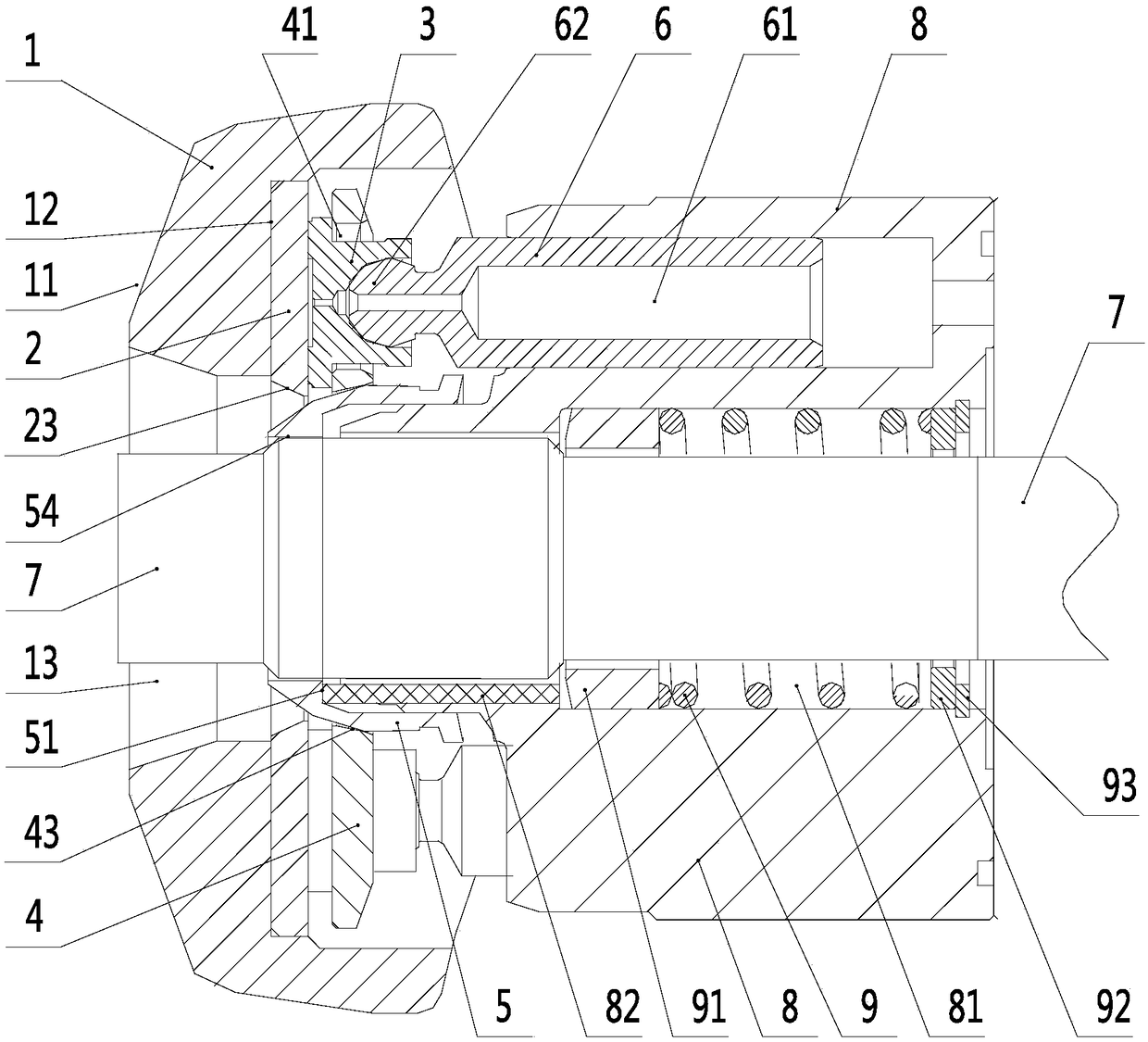
[0035] An axial piston hydraulic pump such as figure 1 As shown, it includes a swash plate 1, a thrust plate 2, a ball joint 5, a rotating shaft 7, a cylinder body 8, a compression pin 82, a spring 9 and a plunger assembly. The plunger assembly includes a plunger 6 and a shoe 3, and the plunger One end of 6 is ball head 62, and slide shoe 3 is wrapped on ball head 62. Sliding shoe 3 is provided with oil shoe oil hole 32, and plunger 6 is also provided with plunger oil hole 61 connected with oil shoe oil hole 32, so that the contact surface of sliding shoe 3 and plunger 6 forms an oil film during operation. Avoid dry rubbing.

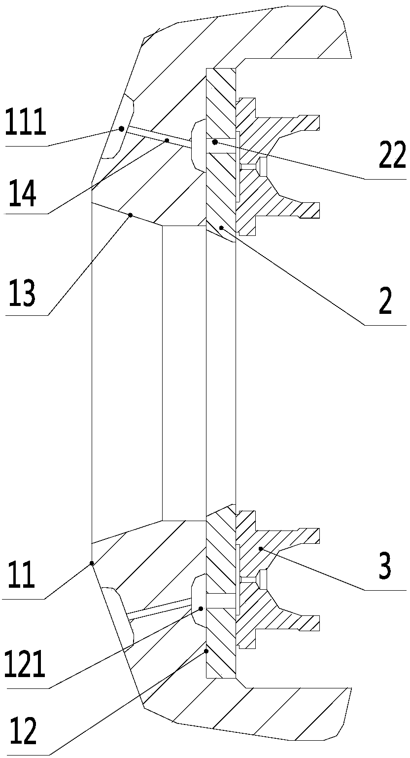
[0036] Such as Figure 1 to Figure 4 As shown, the middle part of the swash plate 1 is provided wit...


PUM


Abstract

The invention provides an axial plunger type hydraulic pump. The axial plunger type hydraulic pump comprises a rotating shaft. A swash plate, a spherical hinge and a cylinder body are sequentially arranged on the rotating shaft. Multiple sliding shoe mounting holes are evenly formed in a return plate. Sliding shoes are sleeved with sliding shoe mounting holes. A thrust plate is mounted between theswash plate and the sliding shoes. A first assembly hole, a second assembly hole, a third assembly hole, a fourth assembly hole and a fifth assembly hole are correspondingly formed in the middles ofthe swash plate, the thrust plate, the spherical hinge, the return plate and the cylinder body. The fifth assembly hole penetrates the two ends of the cylinder body. An elastic element is arranged inthe fifth assembly hole. An elastic element support is arranged at one end of the elastic element, and the other end of the elastic element is connected with a snap spring. The elastic element supportis connected with the bottom face of the spherical hinge through pressing pins. The two end faces of the swash plate are correspondingly matched with the inner wall of a shell of the axial plunger type hydraulic pump and the end face of the thrust plate. The axial plunger type hydraulic pump has the beneficial effects of being simple in structure, low in production cost, and capable of reducing the friction and noise and meanwhile achieving the function of automatic wear compensation of the sliding shoes.

Description

technical field [0001] The invention relates to the technical field of plunger hydraulic pumps, in particular to an axial plunger hydraulic pump. Background technique [0002] In the axial plunger hydraulic pump, the oil suction and discharge of the plunger pump is completed by the reciprocating movement of the plunger in the cylinder. When spraying out, when oil is sucked, the plunger moves through the sliding shoe under the drive of the return plate, so that the volume of the plunger cavity becomes larger and a vacuum is formed to realize oil suction. [0003] In the existing axial plunger hydraulic pumps, the return disc is often fixed by the return disc retaining ring. However, the static hydraulic transmission with the return disc retaining ring structure is difficult to assemble, the yield is low, and the maintenance is inconvenient. There is no automatic compensation function when the shoe wears and becomes thinner. [0004] In addition, in the existing axial plunge...

Claims


Application Information

Patent Timeline
Patent Type & Authority Applications(China)
IPC IPC(8): F04B1/20F04B53/18F04B53/00
CPCF04B1/20F04B1/2014F04B53/18
Inventor 黄泽伟
Owner CHUZHOU YUEDA IND
Why Eureka
Try Eureka