Automatic detection system for power failure

An automatic detection and circuit fault technology, applied in the fault location, detection of faults according to conductor types, measurement of electricity, etc., can solve problems such as phase-to-phase short-circuit expansion accidents, electrical fires, fuse insulation breakdown, etc., to improve power supply continuity, The effect of avoiding further expansion and ensuring reliability

Active Publication Date: 2018-06-12
上海科文斯集成微电有限公司
View PDF5 Cites 6 Cited by
  • Summary
  • Abstract
  • Description
  • Claims
  • Application Information

AI Technical Summary

Problems solved by technology

Single-phase grounding not only affects the normal power supply of users, but also may generate overvoltage, burn out equipment, and even cause phase-to-phase short circuit to expand accidents
[0003] In actual operation, the plastic cloth of the brick factory fell onto the wires due to strong winds, causing the voltage transformers of the substation to burn out, causing equipment damage and large-scale power outages
After a single-phase ground fault occurs, resonant overvoltage may also occur, which may be several times higher than the normal voltage, endangering the insulation of the substation equipment, and in severe cases, the insulation breakdown of the substation equipment may cause a greater accident
[0004] After a single-phase grounding fault occurs, intermittent arcing grounding may occur, resulting in resonant overvoltage and overvoltage several times higher than the normal voltage. The overvoltage will further cause insulation breakdown of the insulator on the line, resulting in a serious short circuit accident. Burn down part of the distribution transformer, cause the lightning arrester and fuse insulation on the line to break down and burn out, and electrical fires may also occur

Method used


Image

  • Automatic detection system for power failure
  • Automatic detection system for power failure
  • Automatic detection system for power failure

Examples


Embodiment Construction

[0042] The present invention will be further described in detail below in conjunction with the accompanying drawings, so that those skilled in the art can implement it with reference to the description.

[0043] It should be understood that terms such as "having", "comprising" and "including" as used herein do not entail the presence or addition of one or more other elements or combinations thereof.

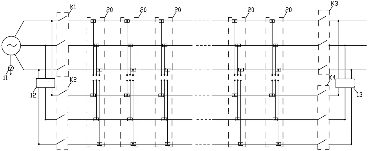
[0044] The invention provides an automatic circuit fault detection system, such as Figure 1-7 As shown, it includes a spare three-phase line, which is set in parallel on the original three-phase line. In this embodiment, two three-phase lines are connected in parallel to build a power supply network. Parallel connection, the power transmission line of the present invention adopts two three-phase power supply lines connected in parallel. After one of the three-phase lines fails, it can be cut off in time without affecting the normal operation of the other transmission line, there...


PUM


Abstract

The invention discloses an automatic detection system for power failure. The system comprises at least two three-phase lines arranged in parallel, a plurality of fault acquisition units, a plurality of fault detection devices and a plurality of fault isolation devices, wherein a neutral point of each three-phase line is provided with a first electrical signal acquisition unit, an input end parallel line of the two three-phase lines is provided with a second electrical signal acquisition unit, an output end parallel line of the two three-phase lines is provided with a third electrical signal acquisition unit; the plurality of fault detection devices comprise a plurality of electrical contact ends insulatedly arranged, the plurality of fault isolation devices are arranged on the upper surface center of the fault detection devices, each fault isolation device comprises a second driving mechanism, a first end of a driving shaft of each second driving mechanism is telescopicly provided witha pair of conductive connecting arms, the lower end of each conductive connecting arm is provided with a first conductive contact head, and each first conductive contact head is selectively connectedwith an electrical contact end. The automatic detection system for power failure guarantees the normal operation of power transmission networks after power transmission lines break down.

Description

technical field [0001] The invention relates to an intelligent detection system, more specifically, the invention relates to an automatic circuit fault detection system. Background technique [0002] Single-phase grounding is a single-phase grounding of 10kV (35kV) small current grounding system. Single-phase grounding fault is the most common fault in power distribution system, which mostly occurs in humid and rainy weather. It is caused by many factors such as tree barriers, single-phase breakdown of insulators on distribution lines, single-phase disconnection, and small animal hazards. Single-phase grounding not only affects the normal power supply of users, but also may generate overvoltage, burn out equipment, and even cause phase-to-phase short circuit to expand accidents. [0003] In actual operation, the plastic cloth of the brick factory fell onto the wires due to strong winds, causing the voltage transformers of the substation to burn out, causing equipment damage...

Claims


Application Information

Patent Timeline
Patent Type & Authority Applications(China)
IPC IPC(8): G01R31/08G01R31/02
CPCG01R31/085G01R31/50
Inventor 储建华高霞
Owner 上海科文斯集成微电有限公司
Why Eureka
Try Eureka