An Optical Frequency Comb Generator with Spectral Line Spacing Equal to Fiber Brillouin Frequency Shift

A technology of Brillouin frequency shift and optical frequency comb, applied in lasers, phonon exciters, nonlinear optics, etc. Frequency comb spectrum line phase noise performance and other issues, to achieve the effect of easy optoelectronic integration, good scalability, and realization of optoelectronic integration

Active Publication Date: 2020-05-15
BEIHANG UNIV
View PDF3 Cites 0 Cited by
  • Summary
  • Abstract
  • Description
  • Claims
  • Application Information

AI Technical Summary

Problems solved by technology

The first is a method based on a mode-locked laser, which requires the construction of a complex resonator, and the output spectrum is easily affected by the external temperature and the loss and dispersion of waveguide media such as optical fibers
The second is the method of using the nonlinear effect in the optical fiber. This method produces a large number of spectral lines, but the excitation of the nonlinear effect in the optical fiber requires high optical power, and the generated optical frequency comb is not highly adjustable.
[0003] Although the above-mentioned methods based on electro-optic modulators can obtain flat optical frequency combs, they all require high-performance, low-noise microwave signal sources to provide driving signals. In this way, not only the cost is high, but also noise will be introduced, which will deteriorate the generated light Phase Noise Performance of Frequency Comb Lines

Method used


Image

  • An Optical Frequency Comb Generator with Spectral Line Spacing Equal to Fiber Brillouin Frequency Shift
  • An Optical Frequency Comb Generator with Spectral Line Spacing Equal to Fiber Brillouin Frequency Shift
  • An Optical Frequency Comb Generator with Spectral Line Spacing Equal to Fiber Brillouin Frequency Shift

Examples


Embodiment Construction

[0014] specific implementation

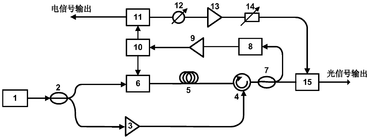
[0015] The scheme of the optical frequency generator proposed by the present invention has been verified through experiments, and the experimental device is as figure 1 As shown, the experimental process and results are described below in conjunction with the accompanying drawings.

[0016] Such as figure 1 As shown, in the experiment, the working wavelength of the tunable continuous wave laser is set to 1550.2nm, and the output power is 14dBm. The 2 ports of the circulator enter the non-zero dispersion-shifted fiber with a length of 2km in reverse, and the output power of the amplifier is 12dBm to stimulate the stimulated Brillouin scattering effect in the non-zero dispersion-shifted fiber. When the -1st order sideband of the phase modulator output is within the gain bandwidth of stimulated Brillouin scattering, this sideband will be amplified. The light output by the optical fiber is input to the 10:90 coupler through the circulator and ...


PUM


Abstract

The invention discloses an optical frequency comb generator with the spectral line interval being equal to optical fiber Brillouin frequency shift. The optical frequency comb generator is characterized in that a continuous wave laser device, an electro-optical phase modulator, an optical fiber, a photoelectric detector and a radio frequency amplifier are utilized to form a feedback loop to generate a radio frequency signal with the oscillation frequency being equal to the optical fiber Brillouin frequency shift, the radio frequency signal is utilized to drive another electro-optical modulatorto generate an optical frequency comb with the spectral line interval being equal to the optical fiber Brillouin frequency shift, and the spectral line interval of the optical frequency comb can be changed by regulating the working wavelength of the laser device or using optical fibers with different Brillouin frequency shifts. Compared with a method for generating the optical frequency comb on the basis of electro-optical modulation, the optical frequency comb generator has the advantages that an additional radio frequency signal for driving the modulator is not needed, and accordingly the optical frequency comb generator is high in stability and low in phase noise, and photoelectric integration can be achieved easily.

Description

technical field [0001] Electro-optic modulation of continuous laser light by radio frequency signal is a common method for generating optical frequency combs. The realization of this method requires an external radio frequency source. The invention relates to an optical frequency comb generating device based on stimulated Brillouin scattering and electro-optic modulation, which uses a continuous wave laser, an electro-optic phase modulator, an optical fiber, a photoelectric detection and a radio frequency amplifier to form an oscillation loop, and the frequency of generation is equal to that of the optical fiber distribution Oscillation mode of Liouin frequency shift, using this signal to drive another electro-optic modulator to generate an optical frequency comb. Therefore, the present invention does not require an external radio frequency signal, and can simultaneously generate a radio frequency signal whose frequency is the fiber Brillouin frequency shift and an optical fre...

Claims


Application Information

Patent Timeline
Patent Type & Authority Patents(China)
IPC IPC(8): G02F1/035G02F1/35G02F1/39H01S3/30
CPCG02F1/035G02F1/353G02F1/39H01S3/302
Inventor 闫娟娟梁爱虎
Owner BEIHANG UNIV
Why Eureka
Try Eureka