Positioning cutting device for bridge construction

A technology for positioning cutting and bridge construction, which is applied in the direction of shearing devices, accessories of shearing machines, manufacturing tools, etc. It can solve the problems of inability to rotate the workpiece and the inability to better adjust the position of the device, and achieve the effect of device safety

Inactive Publication Date: 2018-06-15
GANSU ROAD & BRIDGE CONSTR GROUP
View PDF6 Cites 2 Cited by
  • Summary
  • Abstract
  • Description
  • Claims
  • Application Information

AI Technical Summary

Problems solved by technology

[0005] Aiming at the deficiencies in the prior art, the purpose of the present invention is to provide a positioning cutting device for bridge construction, so as to solve the problem that the cutting machine cannot enable the device to continuously feed materials autonomously and the workpiece on the device cannot be rotated when performing cutting work. And it is impossible to make the device unable to better adjust the position of the device, so that the problem of making the device more perfect and more intelligent

Method used


Image

  • Positioning cutting device for bridge construction
  • Positioning cutting device for bridge construction
  • Positioning cutting device for bridge construction

Examples


Embodiment Construction

[0024]In order to make the technical means, creative features, goals and effects achieved by the present invention easy to understand, the present invention will be further described below in conjunction with specific embodiments.

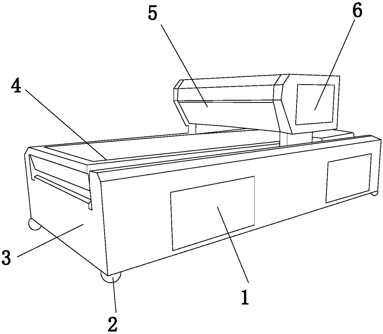
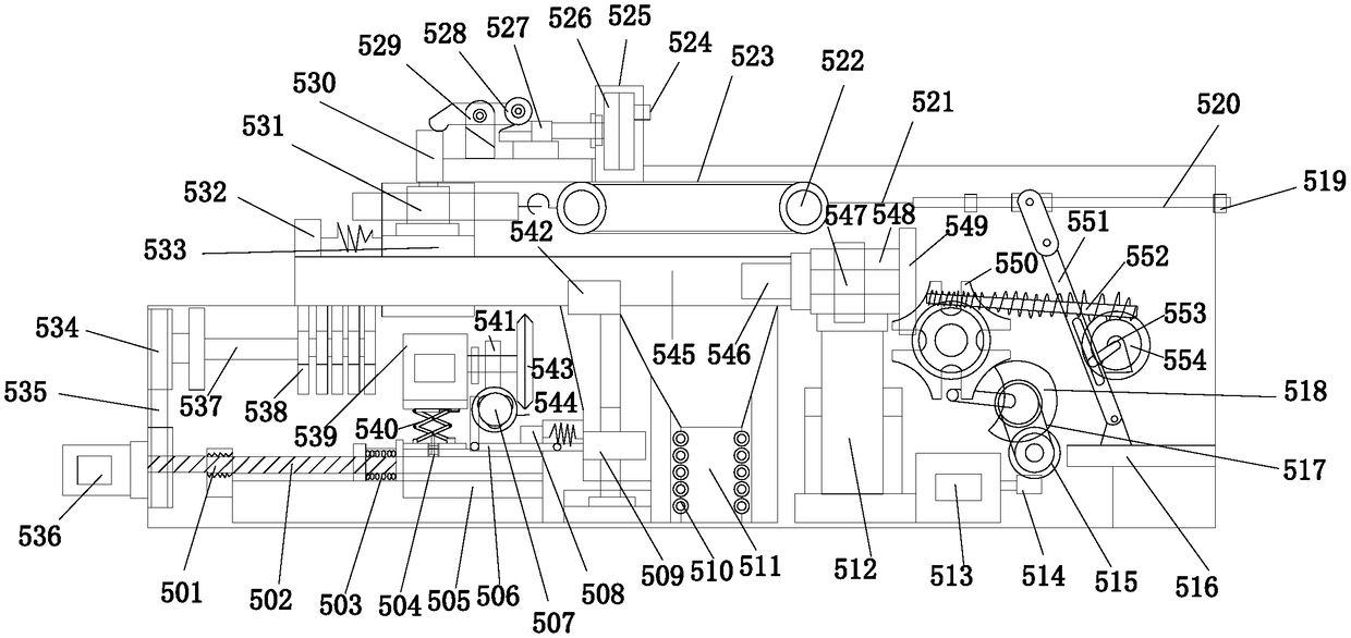
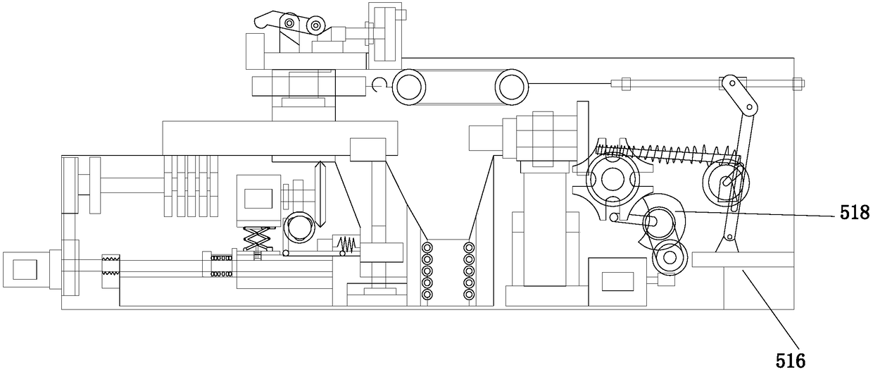
[0025] see Figure 1-Figure 5 , the present invention provides a technical scheme of a positioning cutting device for bridge construction: its structure includes: a wire box 1, a protective pad 2, a device housing 3, a conveyor belt 4, a cutting device 5, and a heat dissipation window 6, and the protective pad 2 is located at The lower surface of the device housing 3 is an integrated structure with it, the electrical box 1 is embedded in the interior of the device housing 3, the conveyor belt 4 is arranged on the upper surface of the device housing 3 and is movably matched with it, and the cutting device 5 is fixedly installed on the upper surface of the device housing 3, and the heat dissipation window 6 is located on the right side of the cutting...


PUM


Abstract

The invention discloses a positioning cutting device for bridge construction. The device structurally comprises an electric wire box, a protection pad, a device shell, a conveying belt, a cutting device body and a cooling window; the protection pad is located on the lower surface of the device shell, the protection pad and the device shell are of an integrated structure, the electric wire box is embedded in the device shell, the conveying belt is arranged on the upper surface of the device shell and is movably matched with the device shell, the cutting device body is fixedly mounted on the upper surface of the device shell, the cooling window is located on the right side face of the cutting device body and is mechanically connected with the cutting device. According to the device, when a cutting machine cuts, the device can carry out continuous feeding, a workpiece on the device can rotate, under the condition that a workpiece is not moved, the position of a tool is adjusted to enablethe position of the device to be better adjusted, and the device is more perfect and more intelligent.

Description

technical field [0001] The invention relates to a positioning cutting device for bridge construction, which belongs to the field of positioning cutting. Background technique [0002] With the development of the modern mechanical processing industry, the requirements for cutting quality and precision are constantly improving, and the requirements for improving production efficiency, reducing production costs, and highly intelligent automatic cutting functions are also increasing. The development of CNC cutting machines must adapt to the requirements of the development of modern machining industry. Cutting machine is divided into flame cutting machine, plasma cutting machine, laser cutting machine, water cutting and so on. The laser cutting machine has the fastest efficiency, the highest cutting precision, and the cutting thickness is generally small. The cutting speed of the plasma cutting machine is also very fast, and the cutting surface has a certain slope. The flame cu...

Claims


Application Information

Patent Timeline
Patent Type & Authority Applications(China)
IPC IPC(8): B23D19/00B23D33/00B23D33/02B23Q7/00B23Q11/00
CPCB23D19/00B23D33/00B23D33/02B23Q7/00B23Q11/0032
Inventor 谢晓燕康谦蒋利亚
Owner GANSU ROAD & BRIDGE CONSTR GROUP
Why Eureka
Try Eureka