Eureka AIR delivers breakthrough ideas for toughest innovation challenges, trusted by R&D personnel around the world.

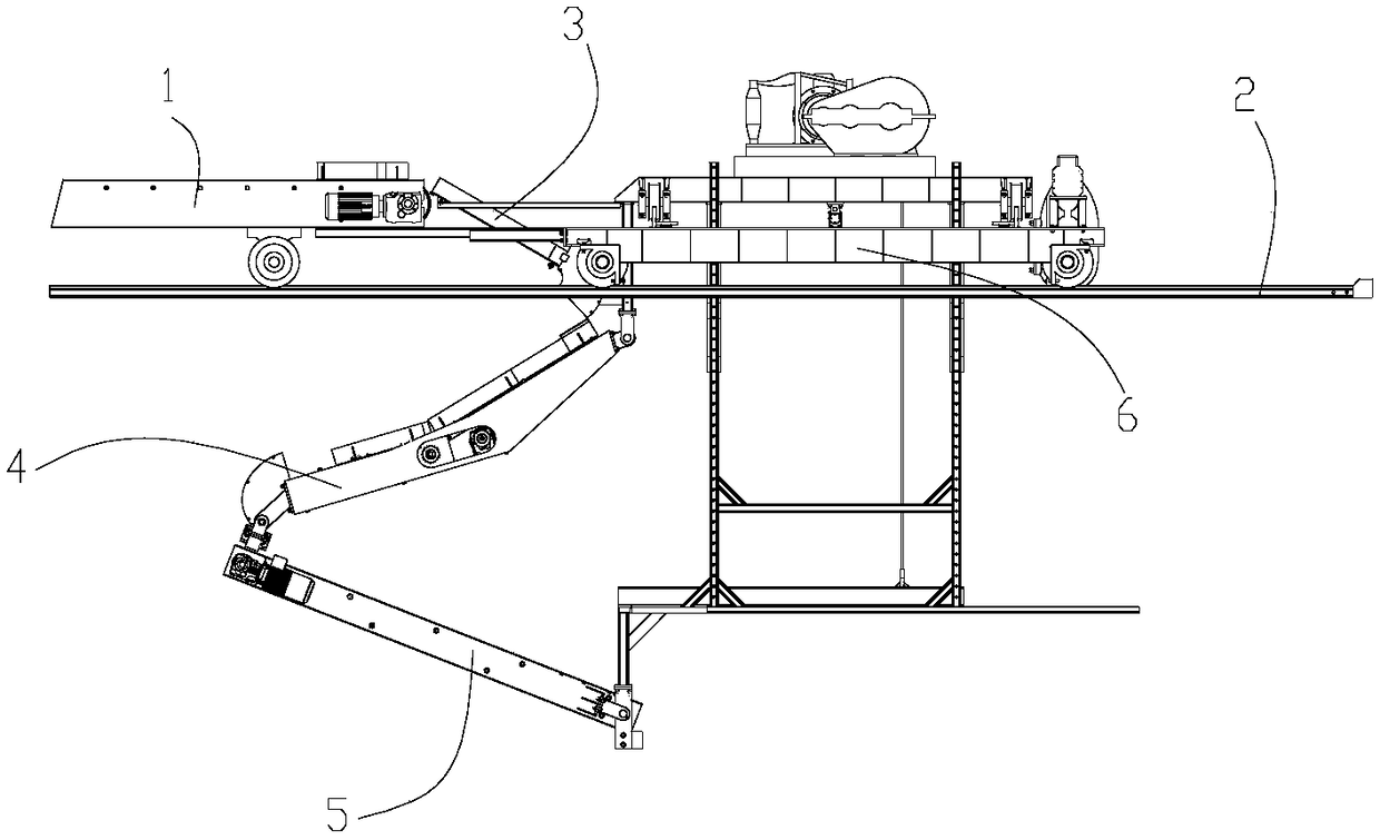
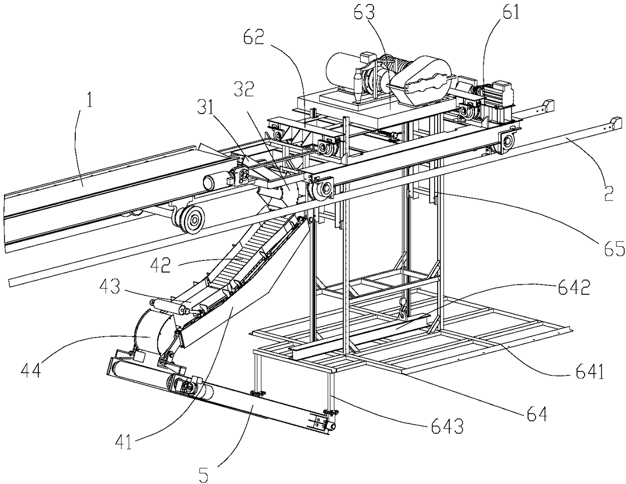
Folding type conveying device on bagged material loading machine in workshop building

A technology of conveying device and car loading machine, which is applied in the direction of conveyor, object stacking, loading/unloading, etc. It can solve the problems of moving the car loading machine back and forth, increasing the difficulty of electrical control and equipment cost, etc., to overcome the long length Effect

Active Publication Date: 2018-06-15
CNBM HEFEI POWDER TECH EQUIP CO LTD
View PDF17 Cites 6 Cited by
  • Summary
  • Abstract
  • Description
  • Claims
  • Application Information

AI Technical Summary

Problems solved by technology

In the process of rising or falling of the palletizing mechanism, the inclination angle of the slope conveyor belt changes, which will inevitably cause the entire loading machine to move forward and backward.
In order to ensure that the palletizing position remains unchanged, the movement of the horizontal track conveyor belt cannot be directly driven by the running device, and it needs to be driven by a separate motor to perform position compensation during the lifting process of the palletizing mechanism, which undoubtedly increases the difficulty of electrical control and equipment. the cost of

Method used


Image

  • Folding type conveying device on bagged material loading machine in workshop building
  • Folding type conveying device on bagged material loading machine in workshop building
  • Folding type conveying device on bagged material loading machine in workshop building

Examples


Embodiment Construction

[0025] In the description of the present invention, unless otherwise specified, the orientation or positional relationship indicated by the terms "upper", "lower", "left", "right", "front", "rear", etc. are only for describing the present invention and simplifying the description, rather than Nothing indicating or implying that the referred device or structure must have a particular orientation should not be construed as limiting the invention. In addition, the terms "first", "second", etc. are used for descriptive purposes only, and should not be construed as indicating or implying relative importance.

[0026] The following preferred embodiments of the present invention will be further described in detail in conjunction with the accompanying drawings. The following preferred modes are used to illustrate the utility model and are not intended to limit the scope of the present invention.

[0027] Such as figure 1 with figure 2 As shown, the folding conveying device of the p...


PUM


Abstract

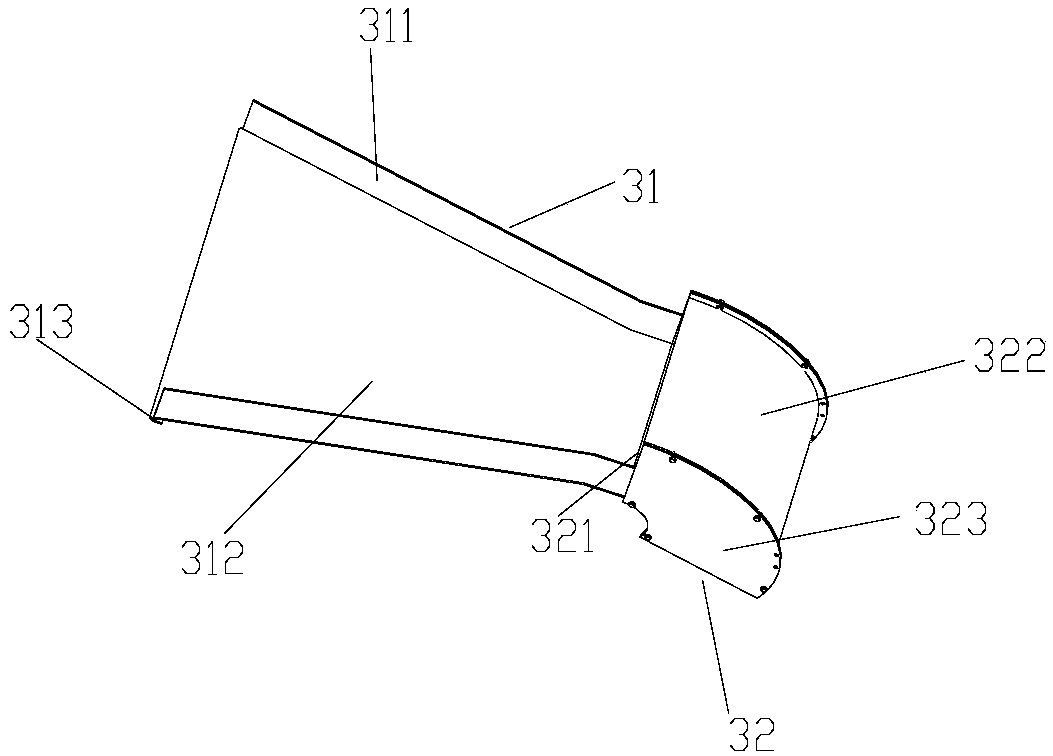
The invention provides a folding type conveying device on a bagged material loading machine in a workshop building. The folding type conveying device comprises a guide rail installed on the workshop building and a conveying mechanism on the guide rail, the guide rail is connected with a three-dimensional moving mechanism driving the conveying mechanism to slide on the guide rail, the tail end of the conveying mechanism is provided with multiple segments of folding conveying mechanisms, the multiple segments of folding conveying mechanisms comprise a reversing slide rail, a bag receiving component and a bag delivering component, wherein the reversing slide rail is connected with the three-dimensional moving mechanism, the bag receiving component is arranged at the lower portion of the reversing slide rail and connected to the three-dimensional moving mechanism, the bag delivering component is connected with the bag receiving component, and the bag delivering component is connected to the lower end of the three-dimensional moving mechanism. According to the folding type conveying device on the bagged material loading machine in the workshop building, folding type conveying of baggedmaterials is realized by means of the multiple segments of folding conveying mechanisms, the defect that a traditional conveyor belt is long is overcome, the multiple segments of folding conveying mechanisms are connected with the three-dimensional moving mechanism, and the multiple segments of folding conveying mechanisms can be made to move in the horizontal, lengthways and up and down positionsto realize material stacking for carriages of any length and width.

Description

technical field [0001] The invention relates to the field of material conveying equipment, in particular to a folding conveying device on a bagged material loading machine in a factory building. Background technique [0002] In order to improve the loading efficiency of bagged cement, reduce labor costs, and reduce the impact of harsh working environments on the human body, many cement plants have adopted semi-automatic or fully automatic loading machines at present, referring to the building materials industry standard "JCT 2048-2011 Bagged Cement Loading Machine", the loading machine mainly includes the track installed on the second floor of the workshop, the horizontal conveyor belt that can move on the track, the slope conveyor belt connected to the end of the horizontal conveyor belt, and the walking device that controls the movement of the horizontal conveyor belt and controls the slope. The lifting device for conveyor belt lifting, the cement bag is transported throug...

Claims


Application Information

Patent Timeline
IPC IPC(8): B65G67/04B65G57/20
CPCB65G57/20B65G67/04B65G2201/0238
Inventor 高霖罗衡何林宋思远凌兴国王学敏王虔虔李永新
Owner CNBM HEFEI POWDER TECH EQUIP CO LTD
Why Eureka
Eureka Blog
Learn More