Eureka AIR delivers breakthrough ideas for toughest innovation challenges, trusted by R&D personnel around the world.

Organic light-emitting material and application thereof

A light-emitting material, organic technology, applied in the direction of light-emitting materials, organic chemistry, electrical components, etc., can solve the problems of low external light-emitting efficiency of OLED, aging of OLED devices, increase production cost, etc., to avoid performance degradation, difficult to age problems, improve The effect of exciton balance

Inactive Publication Date: 2018-06-15
AAC TECH NANJING
View PDF1 Cites 3 Cited by
  • Summary
  • Abstract
  • Description
  • Claims
  • Application Information

AI Technical Summary

Problems solved by technology

Many current TADF material designs must use organic functional groups containing carbazole or triphenylamine or C-N bonds as organic groups for transporting holes or forming HOMO in order to achieve the purpose of HOMO-LUMO separation. However, these groups It is very easy to cause aging of subsequent OLED devices
[0004] In addition, the traditional TADF OLED device contains a host material and a guest TADF material, but since the scattering direction of TADF photons is a random direction, only the light perpendicular to the direction of the ITO substrate has the opportunity to escape from the outside of the device, and the photons in other directions pass through Multiple reflections quench waveguide modes inside the device
In order to improve the luminous efficiency of OLED devices, the traditional method is to attach a layer of light extraction film to the outside of the OLED device. This method not only increases the production cost, but also does not substantially approach the problem of low luminous efficiency outside the OLED.

Method used


Image

  • Organic light-emitting material and application thereof
  • Organic light-emitting material and application thereof
  • Organic light-emitting material and application thereof

Examples


Embodiment Construction

[0031] In order to make the purpose, technical solutions and advantages of the present invention clearer, various embodiments of the present invention will be described in detail below. However, those of ordinary skill in the art can understand that in each implementation manner of the present invention, many technical details are proposed in order to enable readers to better understand the present invention. However, even without these technical details and various changes and modifications based on the following embodiments, the technical solution claimed by each claim of the present invention can also be realized.

[0032] compound

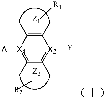
[0033] The first embodiment of the present invention relates to an organic luminescent material, which has a structure represented by general formula (I):

[0034]

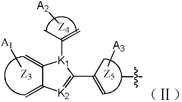
[0035] Among them, X 1 、X 2 Each independently is a C atom or a Si atom; Z 1 ,Z 2 each independently is an unsubstituted or substituted five-membered aromatic ring, six-mem...


PUM


Abstract

The invention relates to the technical field of organic light-emitting devices, and discloses an organic light-emitting material and the application thereof. The organic light-emitting material adoptsthe structure shown as a general formula (I): FORMULA, wherein X1 and X2 are each independently a C atom or a Si atom; Z1 and Z2 are each independently an unsubstituted or substituted five-membered aromatic ring, six-membered aromatic ring or fused ring, and R1 And R2 are each independently an alkyl group, an amino group, an imido group, a deuterated substance or a benzene ring; A is an electron-withdrawing functional group. The organic light-emitting material has a TADF function and a light extraction function at the same time and is a guest material with balanced hole transport and electrontransport capability, and as a light-emitting layer of an OLED, the organic light-emitting material can effectively avoid performance degradation of the device and is beneficial to reduction of the rolloff of the device efficiency; in addition, the organic light-emitting material does not contain functional groups such as carbazole or triphenylamine; the OLED prepared from the organic light-emitting material is good in stability and unlikely to age.

Description

technical field [0001] The invention relates to the technical field of organic electroluminescent devices, in particular to an organic luminescent material and its application. Background technique [0002] Organic electroluminescent device (OLED) emerged as a new generation of flat panel display technology and gradually entered people's field of vision. The initial OLED structure is very simple, that is, anode / luminescent layer (including a light-emitting material) EML / cathode. The device performance of this simple structure is poor, the required start-up voltage is high, and the luminous efficiency is low. Since then, various device structures have been proposed one after another. For example, the basic device structure of the current OLED is: anode / hole injection layer HIL / hole transport layer HTL / EML light emitting layer (host-guest doping system) / ETL electron transport layer / Electron injection layer EIL / cathode. In such a multi-layer device structure, each functional...

Claims


Application Information

Patent Timeline
IPC IPC(8): C09K11/06C07D235/18C07D403/10C07D413/10C07D235/02C07D233/56H01L51/50H01L51/54
CPCC09K11/06C07D233/56C07D235/02C07D235/18C07D403/10C07D413/10C09K2211/1033C09K2211/1044C09K2211/1029C09K2211/1011C09K2211/1007H10K85/615H10K85/654H10K85/657H10K85/6572H10K50/00
Inventor 谢再锋
Owner AAC TECH NANJING
Why Eureka
Eureka Blog
Learn More