Gas power device and method

A technology of gas power and gas pipes, which is applied in the direction of gas turbine devices, turbine/propulsion device inlets, turbine/propulsion device fuel flow channels, etc., and can solve problems such as reduced technical and economic performance, increased irreversible losses, and reduced system efficiency , to achieve the effects of small structure size, reduction of NOX compound emissions, and simple system structure

Pending Publication Date: 2018-06-15
ZHEJIANG SCI-TECH UNIV
View PDF0 Cites 2 Cited by
  • Summary
  • Abstract
  • Description
  • Claims
  • Application Information

AI Technical Summary

Problems solved by technology

[0004] The efficiency of a gas turbine is generally closely related to the pressure ratio and combustion temperature. When the pressure ratio is too high or the combustion temperature is low, the system efficiency will decrease instead.
Increasing the pressure ratio is actually beneficial to reduce the exhaust temperature, but it increases the overall irreversible loss, thereby reducing the system efficiency. In addition, increasing the pressure ratio also greatly increases the size of the equipment and reduces the technical and economic performance.
In addition, appropriately lowering the combustion temperature is conducive to reducing the heat resistance requirements for materials, but when the temperature is lowered, the system efficiency is also greatly reduced, making the gas turbine have to work under high temperature conditions

Method used


Image

  • Gas power device and method
  • Gas power device and method
  • Gas power device and method

Examples


Embodiment 1

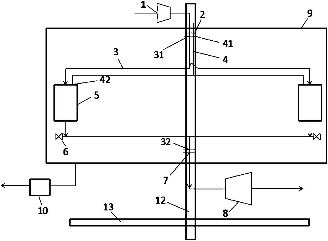
[0052] Embodiment 1, gas powered device, such as figure 1 As shown, it includes a blower 1, a rotary joint, a turbine 8, an air pipe 3, an oil pipe 4, a rotating shaft 12, a protective shell 9, a vacuum pump 10 and an isobaric combustion chamber 5;

[0053] The rotating shaft 12 is fixedly connected with a base 13, and the air blower 1, the turbine 8, the protective casing 9, the vacuum pump 10 and the isobaric combustion chamber 5 are fixed with the base 13, and the base 13 can rotate together with the rotating shaft 12.

[0054] The quantity of gas pipe 3 is one or at least two, and the quantity of oil pipe 4 and equal pressure combustion chamber 5 is all identical with the quantity of gas pipe 3 and corresponds one by one, and each gas pipe 3 is all provided with at least two isothermal combustion chambers 11, and gas pipe 3 and the oil pipe 4 are evenly arranged around the axis position of the rotating shaft 12 as the center.

[0055] The air pipe 3 is provided with an ai...

Embodiment 2

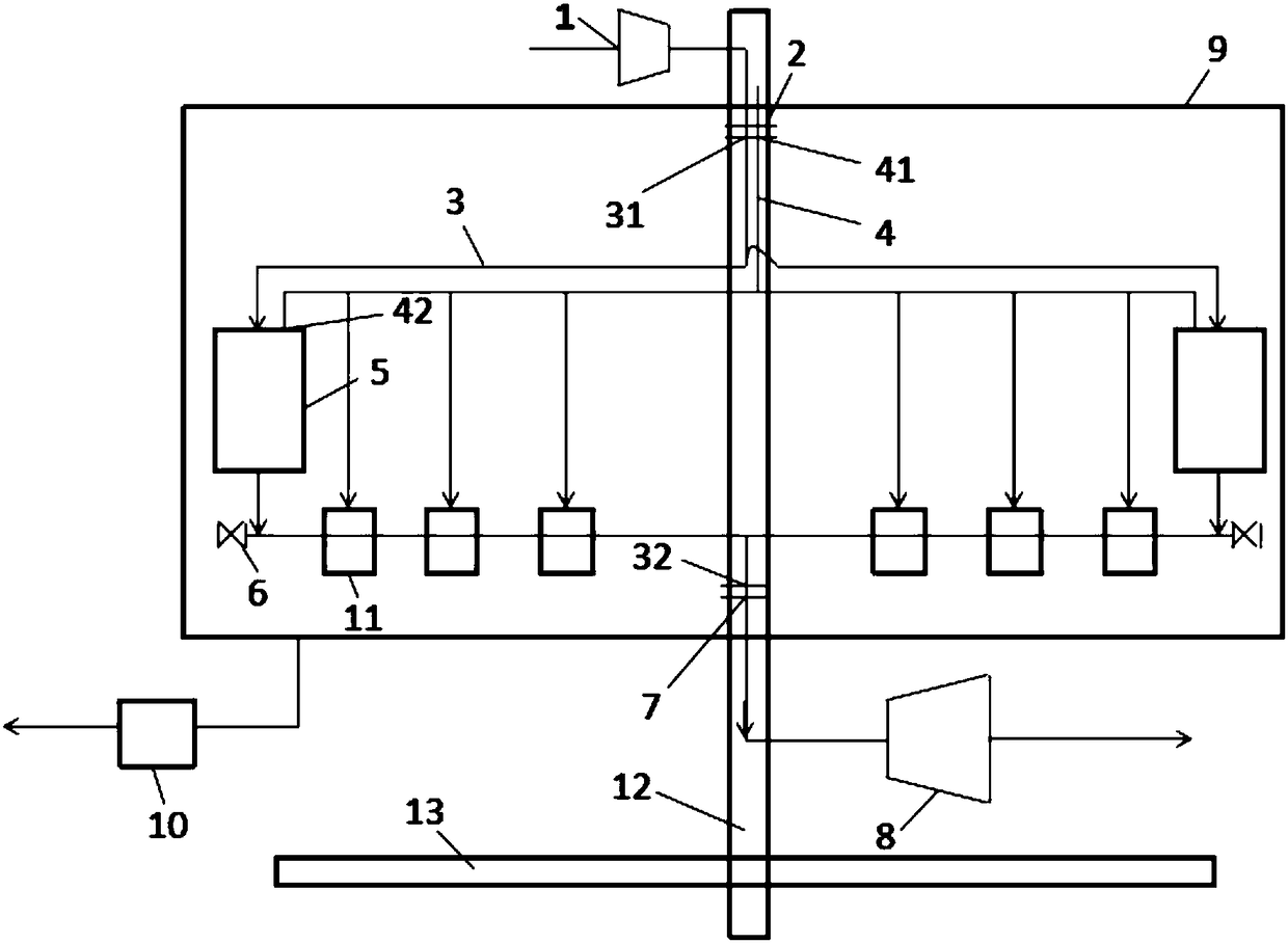
[0071] Embodiment 2, gas powered device, such as figure 2 As shown, it includes a blower 1, a rotary joint, a turbine 8, an air pipe 3, an oil pipe 4, a rotating shaft 12, a protective shell 9, a vacuum pump 10, an isobaric combustion chamber 5 and an isothermal combustion chamber 11.

[0072] The rotating shaft 12 is fixedly connected with a base 13, and the blower 1, the turbine 8, the protective casing 9, the vacuum pump 10, the isobaric combustion chamber 5 and the isothermal combustion chamber 11 are fixed with the base 13, and the base 13 can rotate together with the rotating shaft 12.

[0073] The air pipe 3 is provided with an air pipe inlet 31 and an air pipe outlet 32; the oil pipe 4 is provided with an oil pipe inlet 41 and an oil pipe outlet 42;

[0074] The air inlet of the blower 1 is connected to the external atmosphere, and the air outlet of the blower 1 passes through the rotary joint 2 through the pipe and then communicates with all air pipe inlets 31; the e...

Embodiment 3

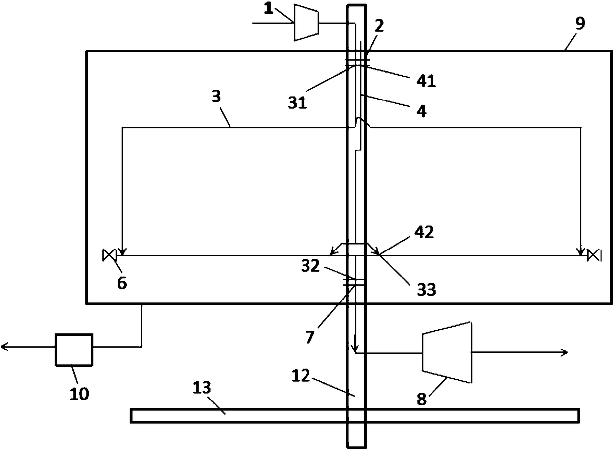
[0089] Embodiment 3, gas powered device, such as image 3 As shown, it includes a blower 1, a rotary joint, a turbine 8, an air pipe 3, an oil pipe 4, a rotating shaft 12, a protective shell 9 and a vacuum pump 10;

[0090] The rotating shaft 12 is fixedly connected with a base 13 , and the air blower 1 , the turbine 8 , the protective casing 9 and the vacuum pump 10 are fixed with the base 13 , and the base 13 can rotate together with the rotating shaft 12 .

[0091] Air pipe 3 is provided with air pipe inlet 31, air pipe oil injection port 33 and air pipe outlet 32; oil pipe 4 is provided with oil pipe inlet 41 and oil pipe oil outlet 42; the rotary joint includes rotary joint one 2 and rotary joint two 7 .

[0092] The air inlet of the blower 1 is connected to the external atmosphere, and the air outlet of the blower 1 passes through the rotary joint 2 through the pipe and then communicates with all air pipe inlets 31; the external oil supply pipeline passes through the ro...


PUM


Abstract

The invention provides a gas power device. The gas power device comprises an air supply machine, rotating joints, a turbine, a gas pipe, an oil pipe and a rotating shaft; an air outlet of the air supply machine communicates with a gas inlet of the gas pipe after penetrating through the first rotating joint through a pipe; an external oil supply pipeline communicates with an oil inlet of the oil pipe after passing through the first rotating joint; an oil outlet of the oil pipe communicates with a pipeline of the gas pipe; and a gas outlet of the gas pipe communicates with an intake port of theturbine through a pipe after passing through the second rotating joint. The invention further provides a gas power method; oil enters the oil pipe; air enters the air pipe through the air supply machine; and after the oil and the air are mixed for combustion, power is outwards output after pressure energy is released from the turbine. The system structure is simple; and a simple pipeline is used for replacing a complicated impeller runner, so that higher efficiency is achieved under the condition of high pressure ratio, and the higher pressure ratio can be adopted.

Description

technical field [0001] The invention relates to the technical field of energy and power, in particular to a gas power device and method. Background technique [0002] Gas turbine is a widely used internal combustion power machine with the characteristics of high efficiency and compact structure. A gas turbine is mainly composed of three major components: a compressor, a combustion chamber, and a turbine. The cycle composed of these three components is called a simple cycle, and most gas turbines generally use a simple cycle. [0003] When the gas turbine is working, the compressor inhales air from the outside atmosphere. After adiabatic compression, the temperature and pressure of the air rise, and then the compressed air is sent into the combustion chamber, where it absorbs the heat released by the combustion of fuel in the combustion chamber and becomes a high-temperature and high-pressure gas. The high-temperature and high-pressure gas then enters the turbine and expands...

Claims


Application Information

Patent Timeline
IPC IPC(8): F02C7/04F02C7/22F02C3/14
CPCF02C7/04F02C3/14F02C7/222
Inventor 王厉
Owner ZHEJIANG SCI-TECH UNIV
Why Eureka
Try Eureka