Virtual inductor and virtual capacitor power distribution method of three-port converter

A technology of virtual inductance and virtual capacitor, applied in battery circuit devices, current collectors, electric vehicles, etc., can solve problems such as failure, increase in power transmission links, and inability to use filter methods directly, so as to extend service life and reduce output fluctuations. , the effect of smoothing transient power fluctuations

Inactive Publication Date: 2018-06-15
HARBIN INST OF TECH
View PDF4 Cites 13 Cited by
  • Summary
  • Abstract
  • Description
  • Claims
  • Application Information

AI Technical Summary

Problems solved by technology

However, this method fails when the target power is unknown. For example, in a DC microgrid, the system operation mode includes the constant voltage control working state of the energy storage unit. At this time, the output power of the energy storage unit is shared by the power of the load and other units in the system. decided, the simple filter approach will not work directly with
[0004] At the same time, the battery and super capacitor in the hybrid energy storage system need to realize power control through the corresponding bidirectional converter. In the DC microgrid, the more common interface converter solution can use two buck / boost bidirectional capacitor to the DC bus, but when exchanging energy between the battery and the super capacitor, two converters are required, resulting in an increase in the power transmission link

Method used


Image

  • Virtual inductor and virtual capacitor power distribution method of three-port converter
  • Virtual inductor and virtual capacitor power distribution method of three-port converter
  • Virtual inductor and virtual capacitor power distribution method of three-port converter

Examples


specific Embodiment approach 1

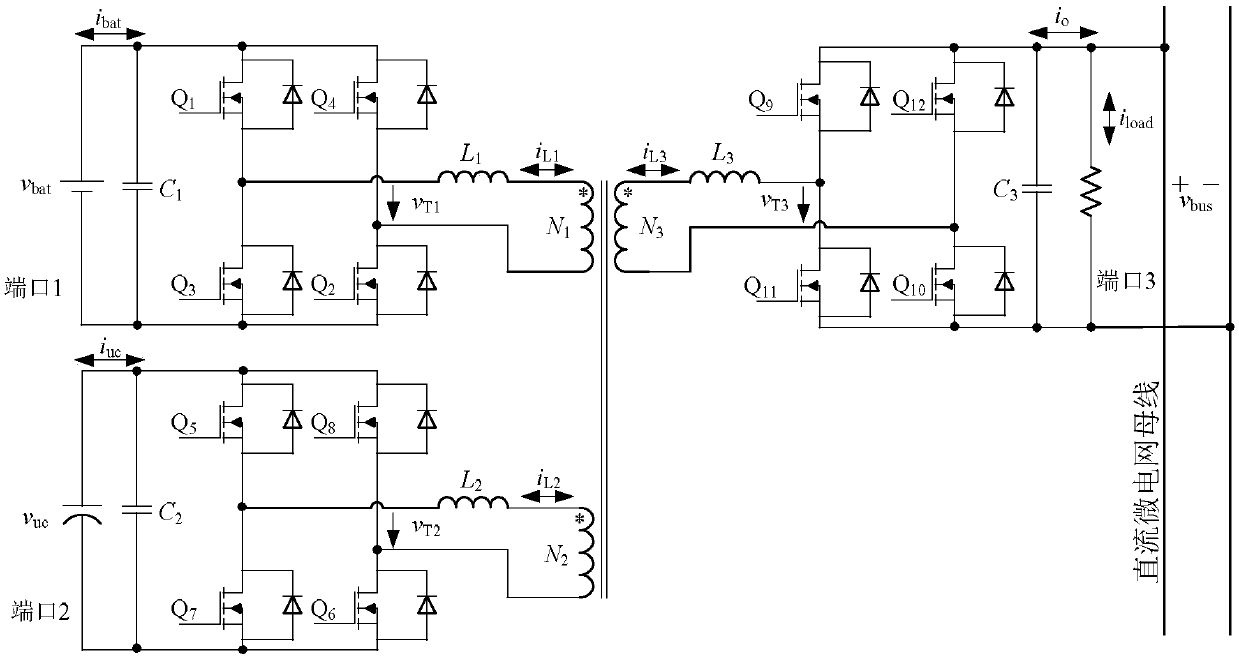
[0017] Specific implementation mode one: combine Figure 1 to Figure 5 To describe this embodiment, in figure 1 Among them, the three-port converter includes primary coil N1, primary coil N2, secondary coil N3, switch tube Q1 to switch tube Q12, twelve diodes, inductor L1, inductor L2, inductor L3, capacitor C1, capacitor C2 and capacitor C3 ;

[0018] Capacitor C1, capacitor C2 and capacitor C3 are respectively connected in parallel at port 1, port 2 and port 3;

[0019] The sources and drains of the switching tubes Q1 to Q12 are respectively connected in parallel with twelve diodes;

[0020] The switching tube Q1 to the switching tube Q4 and the inductor L1 are connected to both sides of the primary coil N1, the switching tube Q5 to the switching tube Q8 and the inductor L2 are connected to both sides of the primary coil N2, the switching tube Q9 to the switching tube Q12 and the inductor L3 are connected to the primary and secondary Both sides of coil N3.
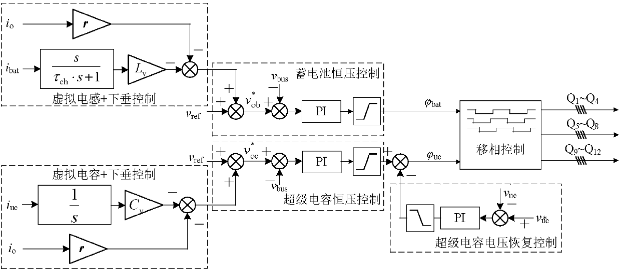
[0021] A vir...


PUM


Abstract

The invention discloses a virtual inductor and virtual capacitor power distribution method of a three-port converter, and relates to a technology of distributing the power of a three-port converter which accesses a direct current micro power grid, for realizing reasonable distribution of the power for a hybrid energy storage system which accesses the direct current micro power grid through the three-port converter. The virtual inductor and virtual capacitor power distribution method of a three-port converter is characterized in that in an energy storage unit, when the voltage of a direct current bus is stable, the real-time current feedback values at the low voltage side of the three-port converter are used to form a virtual inductor and a virtual capacitor; after the virtual capacitor iscombined with sagging control, after constant voltage control, the virtual capacitor is combined with super capacitor voltage recovery control again to become the other input terminal of phase shift control; and the output terminal of phase shift control respectively acts on a switch tube Q1 to a switch tube Q12 in the three-port converter, so as to achieve reasonable distribution of hybrid energystorage power. The virtual inductor and virtual capacitor power distribution method of a three-port converter has the advantages of realizing reasonable distribution of power, and being suitable fora direct current hybrid energy storage system.

Description

technical field [0001] The invention relates to a power distribution technology after a three-port converter is connected to a DC microgrid. Background technique [0002] Batteries and supercapacitors have the characteristics of high capacity density and high power density respectively. The hybrid energy storage system composed of the characteristics of the two can realize complementary advantages and improve the output performance and operating life of the energy storage device. The application of hybrid energy storage systems in power systems has been widely studied. Batteries can be used to provide long-term energy buffers to support the energy balance of power systems, and supercapacitors can be used to provide transient energy buffers to stabilize short-term and medium-term scales of the system. power fluctuations, thereby improving the transient performance of the system. [0003] For the power allocation of hybrid energy storage systems, some scholars have proposed a...

Claims


Application Information

Patent Timeline
Patent Type & Authority Applications(China)
IPC IPC(8): H02J1/14H02J7/34
CPCH02J1/14H02J7/345
Inventor 王盼宝丁四宝王凯峰刘鸿鹏刘桂花王卫徐殿国
Owner HARBIN INST OF TECH
Why Eureka
Try Eureka