
Permanent magnetic engine

A technology of motors and permanent magnets, applied in the direction of electromechanical devices, electrical components, etc., can solve the problems of high energy conversion efficiency, complex structure, and consumption of non-renewable energy, and achieve the effect of simple structure, low production cost and good effect

Inactive Publication Date: 2018-06-15
陈义照
View PDF0 Cites 0 Cited by
  • Summary
  • Abstract
  • Description
  • Claims
  • Application Information

AI Technical Summary

Problems solved by technology

[0003] The engine has gone through three stages: steam engine, external combustion engine and internal combustion engine. Most of the existing engines are internal combustion engines, such as gasoline engines, diesel engines and jet engines, which basically use the chemical energy of fuel as the energy source. The structure is relatively complex and the energy conversion efficiency is high. , need to consume non-renewable energy, and the emissions produced after its combustion have caused increasingly serious harm to human beings
[0004] The magnetic field generated by the magnet is a vector field continuously distributed in a certain space area. The interaction between the magnets uses the magnetic field as the medium to exert force on each other. , there is no report on an engine designed using the principle of magnetic homopolar mutual repulsion

Method used


Image

  • Permanent magnetic engine

Examples


Embodiment Construction

[0014] The present invention will be further described below through examples and in conjunction with the accompanying drawings, but not as a limitation of the present invention.

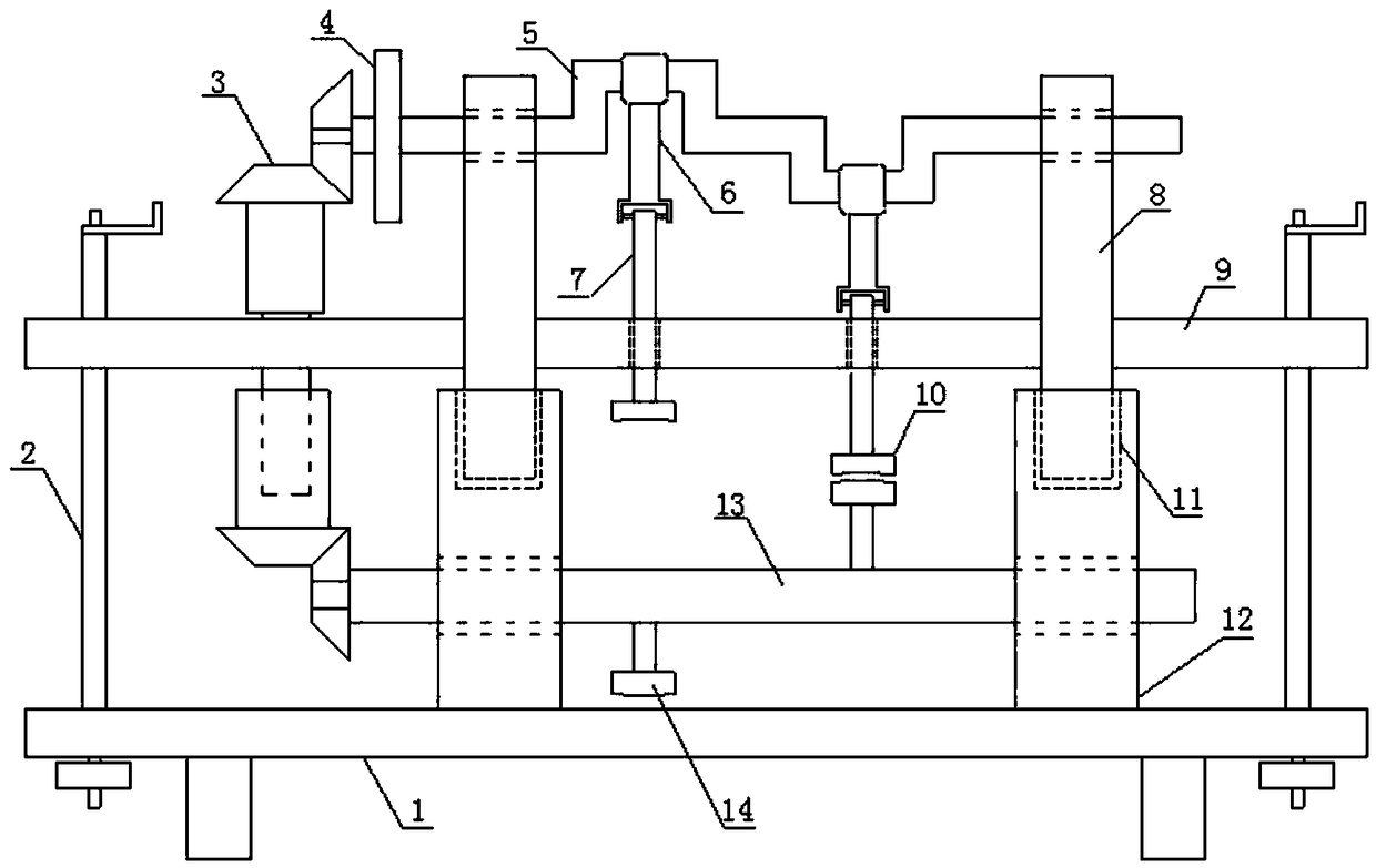
[0015] exist figure 1 In the shown structure, the designed permanent magnet motor of the present invention includes a frame, and the frame is divided into a lower frame and an upper frame, and the lower frame includes a base 1, and two support seats 12 are set on the base to play a role Supporting function, the top of the support seat is provided with jack 11, and the horizontal direction between the support seats is connected to the rotating shaft 13 through the bearing. Rotating permanent magnets 14 are arranged respectively in the opposite direction (that is, the angle between the rotating permanent magnets is 180 degrees). The linkage mechanism makes the lifting screw rotate synchronously; the upper frame includes a horizontal lifting seat 9, which is located above the support seat 12, and its ...


PUM


Abstract

The invention belongs to the power equipment field, and relates to a permanent magnetic engine. The permanent magnetic engine includes a frame, wherein the frame is divided into a lower frame and an upper frame; the lower frame includes a pedestal; support bases on the pedestal are connected with a rotating shaft through bearings; a rotation permanent magnet is arranged on the rotating shaft; lifting screws are movably arranged on the pedestal; the upper frame includes a horizontal lifting base; the horizontal lifting base is connected with the lifting screws through threads; movable support frames are fixedly connected with the horizontal lifting base; the movable support frames are connected with a crankshaft through bearings; a connecting rod shaft neck of the crankshaft is movably provided with a connecting rod; the other end of the connecting rod is movably provided with a reciprocating lever; a reciprocating permanent magnet is arranged at the front end of the reciprocating lever; and the crankshaft is provided with a flywheel and is connected with the rotating shaft through a gear drive mechanism. According to the principle that the same magnetic poles are repellent to eachother, the permanent magnetic engine integrates the rotating shaft with the crankshaft so as to enable the same poles of different permanent magnet materials to be mutually attached to be repellent toeach other, so as to enable the rotating shaft to obtain the rotation power to output the power to the outside to achieve the effect of taking the magnetic force as the power source and converting the power source into mechanical energy.

Description

technical field [0001] The invention belongs to the field of power equipment, and relates to a motor, in particular to a permanent magnet motor which obtains power by the action of a magnetic field. Background technique [0002] Power machinery is a mechanical device that converts energy in nature into mechanical energy to perform work, such as wind machinery, hydraulic machinery and engines, etc., which play an extremely important role in our life and production. Among them, engines are widely used in the world. A kind of power equipment, generally using wind power, water power or fuel chemical energy as the energy source. [0003] The engine has gone through three stages: steam engine, external combustion engine and internal combustion engine. Most of the existing engines are internal combustion engines, such as gasoline engines, diesel engines and jet engines, which basically use the chemical energy of fuel as the energy source. The structure is relatively complex and the...

Claims


Application Information

Patent Timeline
IPC IPC(8): H02K53/00
CPCH02K53/00
Inventor 陈义照
Owner 陈义照
Learn More