
High pressure steam pipe cutting device for treating carbon tetrachloride

A high-pressure steam and cutting device technology, applied in welding equipment, gas flame welding equipment, metal processing equipment, etc., can solve the problems of slow delivery time, high cost, and low cutting efficiency.

Inactive Publication Date: 2018-06-19
XUZHOU UNIV OF TECH
View PDF5 Cites 12 Cited by
  • Summary
  • Abstract
  • Description
  • Claims
  • Application Information

AI Technical Summary

Problems solved by technology

Due to human factors, the cutting speed is not stable, resulting in uneven cutting and low cutting efficiency, which affects the cutting quality; and working under high temperature conditions and dusty conditions will cause great harm to the human body
[0003] Due to many problems such as low cutting efficiency, high labor intensity, and unstable cutting quality in the traditional manual cutting method, it has been gradually replaced by automatic cutting devices. The device uses a three-claw plate and a pneumatic cylinder to fix the workpiece, which will cause many problems such as slow loading time and inability to guarantee cutting quality.

Method used


Image

  • High pressure steam pipe cutting device for treating carbon tetrachloride
  • High pressure steam pipe cutting device for treating carbon tetrachloride
  • High pressure steam pipe cutting device for treating carbon tetrachloride

Examples


Embodiment 1

[0072] Prepare the acetylene connecting pipe 8-5-4 of the present invention according to the following steps, and in parts by weight:

[0073] Step 1: In the continuous stirred tank reactor, add 323.7 parts of ultrapure water and 115.1 parts of 2-methyldodecylaldehyde, start the mixer in the continuous stirred tank reactor, set the speed at 116rpm, start The heat conduction oil heater in the continuous stirred tank reactor raised the temperature to 131.7°C, added 118.4 parts of 2-methoxy-3-methylpyrazine and stirred evenly, and reacted for 108.1 minutes, then added 2-[(methylpyrazine Esteramino)-[2-nitro-5-(n-thiopropyl)-phenylimino] methylamino] 114.1 parts of ethyl sulfuric acid, the flow rate is 107.6m 3 The xenon gas per min was 108.1 minutes; after that, 117.0 parts of yeast ribonucleic acid were added to the continuous stirred tank reactor, and the heat conduction oil heater in the continuous stirred tank reactor was started again to raise the temperature to 148.4°C, kep...

Embodiment 2

[0080] Prepare the acetylene connecting pipe 8-5-4 of the present invention according to the following steps, and in parts by weight:

[0081] Step 1: In the continuous stirred tank reactor, add 548.0 parts of ultrapure water and 157.8 parts of 2-methyldodecylaldehyde, start the mixer in the continuous stirred tank reactor, set the speed at 162rpm, start The heat conduction oil heater in the continuous stirred tank reactor raised the temperature to 132.0°C, added 227.9 parts of 2-methoxy-3-methylpyrazine and stirred evenly, and reacted for 119.8 minutes, then added 2-[(methylpyrazine Esteramino)-[2-nitro-5-(n-thiopropyl)-phenylimino] methylamino] 131.6 parts of ethyl sulfuric acid, the flow rate is 148.6m 3 The xenon gas per min was 119.8 minutes; after that, 174.5 parts of yeast ribonucleic acid were added to the continuous stirred tank reactor, and the heat conduction oil heater in the continuous stirred tank reactor was started again to raise the temperature to 181.9°C, and...

Embodiment 3

[0088] Prepare the acetylene connecting pipe 8-5-4 of the present invention according to the following steps, and in parts by weight:

[0089] Step 1: In the continuous stirred tank reactor, add 323.9 parts of ultrapure water and 115.9 parts of 2-methyldodecylaldehyde, start the mixer in the continuous stirred tank reactor, set the speed at 116rpm, start The heat conduction oil heater in the continuous stirred tank reactor raised the temperature to 131.9°C, added 118.9 parts of 2-methoxy-3-methylpyrazine and stirred evenly, and reacted for 108.9 minutes, then added 2-[(methylpyrazine Esteramino)-[2-nitro-5-(n-thiopropyl)-phenylimino] methylamino] 114.9 parts of ethyl sulfuric acid, the flow rate is 107.9m 3 xenon gas per min for 108.9 minutes; then add 117.9 parts of yeast ribonucleic acid into the continuous stirred tank reactor, start the heat conduction oil heater in the continuous stirred tank reactor again, make the temperature rise to 148.9°C, keep it warm for 108.9 minu...


PUM

PropertyMeasurementUnit
Slopeaaaaaaaaaa
Particle sizeaaaaaaaaaa

Abstract

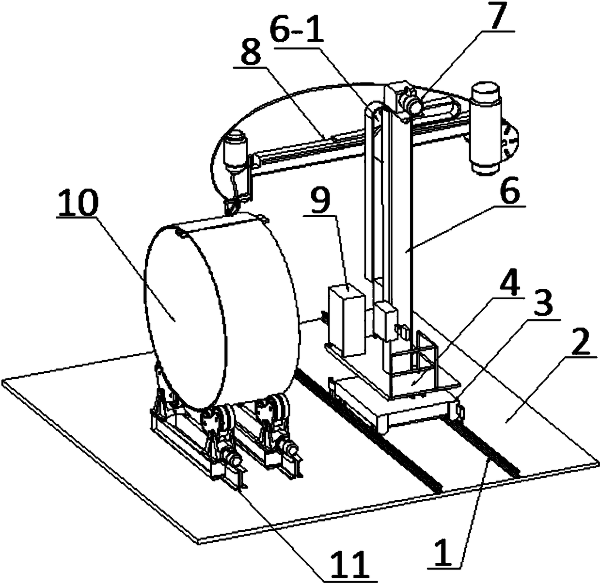
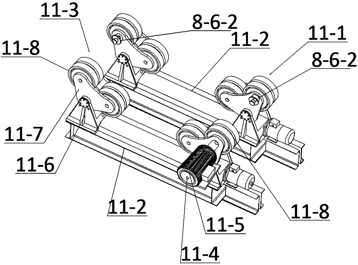
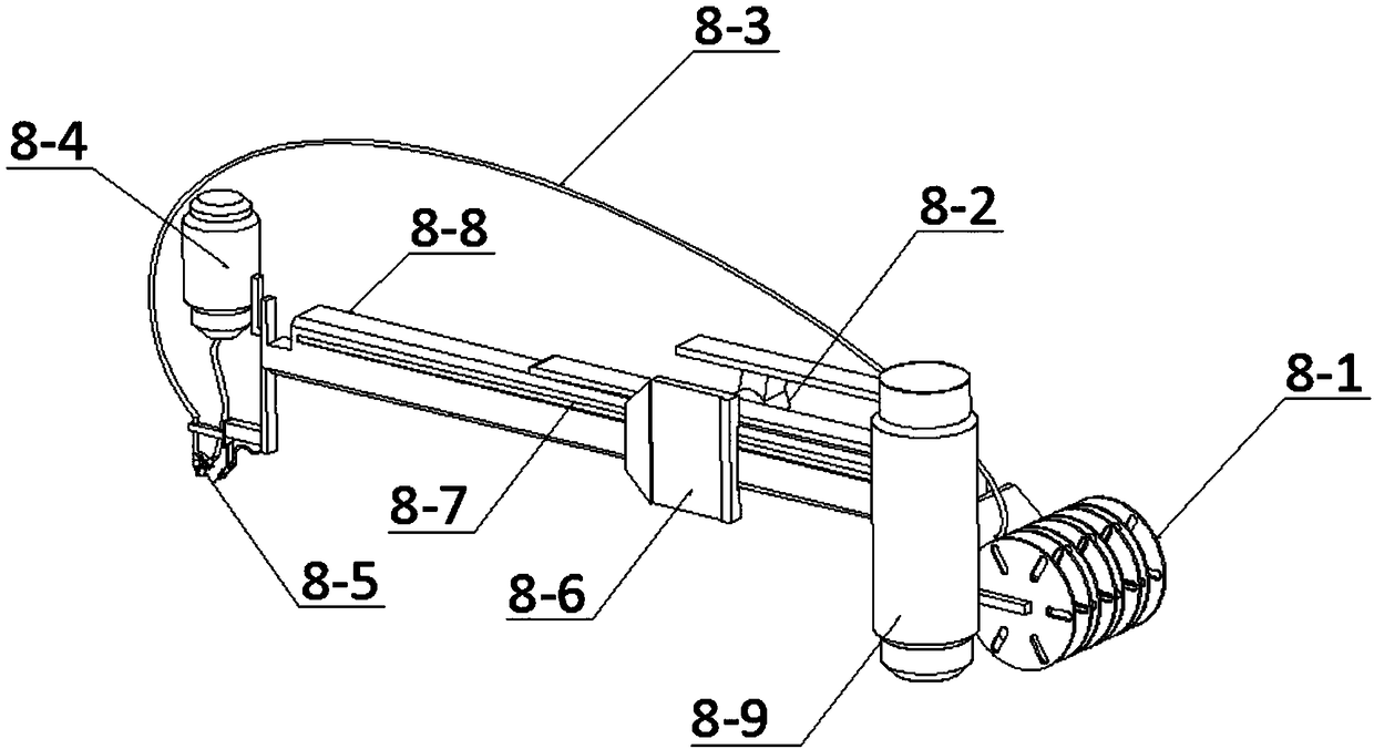
The invention relates to a high pressure steam pipe cutting device for treating carbon tetrachloride. A workpiece fixture is fixedly connected to the left side of the upper part of a fixing plate; a rotary platform is rotatably connected to the upper part of a moving trolley through a rotary shaft fixedly connected to the lower part of the rotary platform; a support pillar is fixedly arranged on the front side of the upper part of the rotary platform; a vertical slideway is arranged on the front side of the support pillar; a winch is fixedly arranged on the top part of the support pillar; a mechanical arm is formed by a fixing arm and a sliding arm; a cutting gun nozzle is fixedly connected to the lower part of the left end of the sliding arm; a reel is fixedly connected to the right end of the fixing arm; two sliding chutes II extending vertically and having T-shaped cross sections are arranged on one side, close to the slideway, of a sliding block; two slide rails with T-shaped crosssections are slidably assembled into the two sliding chutes II; the upper ends and the lower ends of the two slide rails are fixedly connected with the upper end and the lower end of the slideway; and two lubricating oil filling devices corresponding to the two sliding chutes II are fixedly arranged on the front side of the sliding block. The device is convenient in operation process, high in operation efficiency, and suitable for cutting circular workpieces.

Description

technical field [0001] The invention belongs to the technical field of cutting equipment, and in particular relates to a high-pressure steam pipe cutting device for treating carbon tetrachloride. Background technique [0002] When cutting steam round pipes by traditional manual methods, since the outer contour of the round pipe is a circumferential surface, the surface of the round pipe is also cut as an arc surface. Cutting; or the round tube does not move, and the cutting gun surrounds the round tube to cut its outer contour surface. Due to human factors, the cutting speed is not stable, resulting in uneven cutting and low cutting efficiency, which affects the cutting quality; and working under high temperature and dusty conditions will cause great harm to the human body. [0003] Due to many problems such as low cutting efficiency, high labor intensity, and unstable cutting quality in the traditional manual cutting method, it has been gradually replaced by automatic cutt...

Claims


Application Information

Patent Timeline
IPC IPC(8): B23K7/00B23K7/10
CPCB23K7/00B23K7/10B23K7/107
Inventor 梁峙梁骁马捷韩宝平刘喜坤许旭张明胜陈兴祥董平
Owner XUZHOU UNIV OF TECH
Learn More