High-bearing universal joint, mechanical arm joint and flexible mechanical arm

A universal joint, high load-bearing technology, applied in the field of robots, can solve the problems of small load-carrying capacity, under-actuated, complex structural design, etc., and achieve the effect of improving load capacity

Active Publication Date: 2018-06-19
HARBIN INST OF TECH SHENZHEN GRADUATE SCHOOL
View PDF9 Cites 12 Cited by
  • Summary
  • Abstract
  • Description
  • Claims
  • Application Information

AI Technical Summary

Problems solved by technology

In actual use, the bearing capacity of the first and second types of joints is small, making the joints relatively fragile. Although the bearing capacity of the third type of joint is high, the degree of freedom of rotation around the direction of the arm among the three degrees of freedom of the ball joint is limited when driving. I

Method used


Image

  • High-bearing universal joint, mechanical arm joint and flexible mechanical arm
  • High-bearing universal joint, mechanical arm joint and flexible mechanical arm
  • High-bearing universal joint, mechanical arm joint and flexible mechanical arm

Examples


Embodiment 1

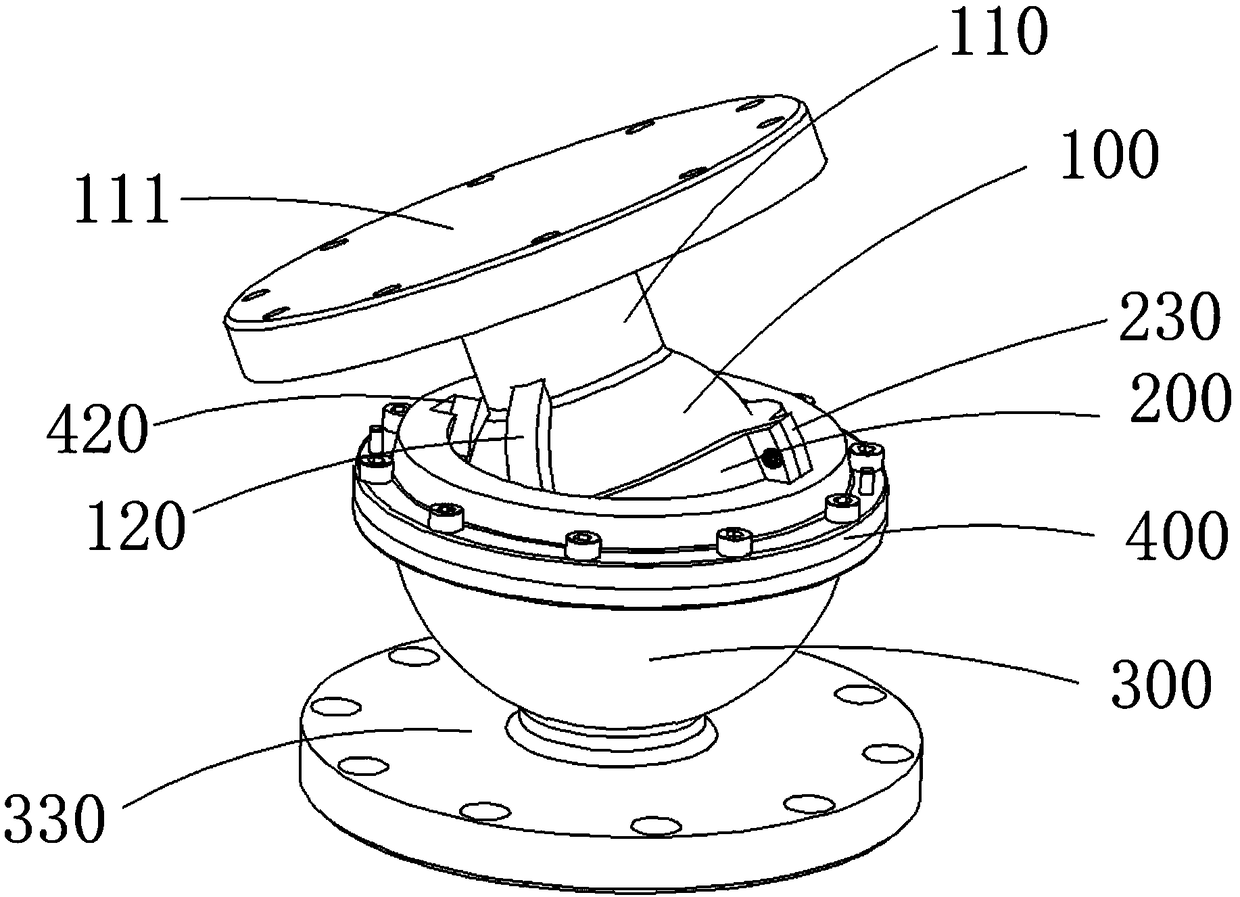
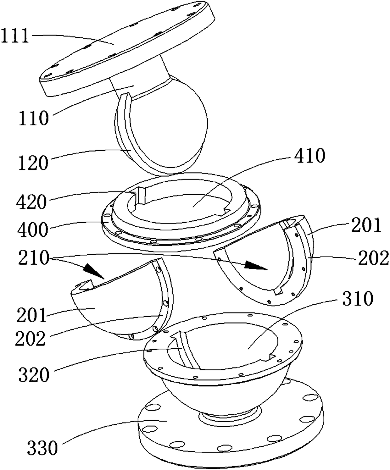
[0030] figure 1 It is a schematic diagram of the overall structure of an embodiment of the high-load universal joint of the present invention, figure 2 for figure 1 The disassembled schematic diagram of the embodiment shown, while referring to figure 1 , 2 , a high-load universal joint, including a first sliding ball 100 , a second sliding ball 200 , a ball seat 300 and a gland 400 .

[0031] The first sliding ball 100 is a solid spherical member, on which a connecting portion 110 is fixedly arranged for connecting with an external member. The second sliding ball 200 includes a first cavity 210 whose inner surface is a spherical surface. The first sliding ball 100 is rotatably arranged in the first cavity 210 and fits with the inner surface of the first cavity 210. The first sliding ball 100 Can slide along the inner surface of the first cavity 210, compared with the cross joint in the prior art, the spherical contact provides a larger contact area for the movement betwee...

Embodiment 2

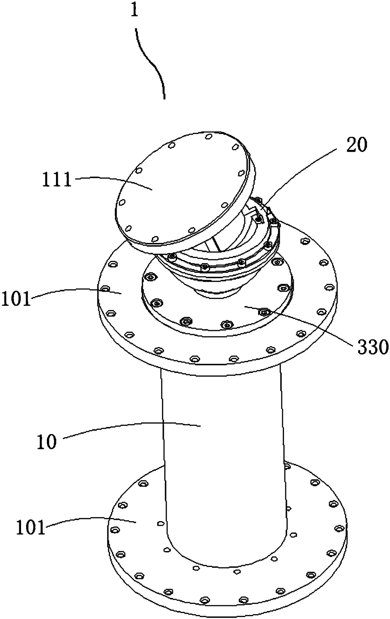
[0042] image 3 It is a structural schematic diagram of an embodiment of the mechanical arm joint of the present invention, refer to image 3 In this embodiment, the mechanical arm joint 1 includes a joint body 10 and a universal joint 20. The universal joint 20 in this embodiment is the high-load universal joint described in the first embodiment above, which is beneficial to improve the bearing capacity of the mechanical arm joint , wherein the connecting body includes the first connecting disk 111 , the ball seat includes the second connecting disk 330 , and the condyle body 10 is fixedly connected to the first connecting disk 111 or the second connecting disk 330 . The first connecting plate 111 and the second connecting plate 330 have the same structure, which can shorten the machining cycle and reduce the cost, and can be installed with any one of them when installing the condyle body 10 without considering the installation sequence, which is conducive to improving assemb...

Embodiment 3

[0044] Figure 4 It is a structural schematic diagram of an embodiment of the flexible robotic arm of the present invention, refer to Figure 4 , the flexible mechanical arm of this embodiment includes a driving device and several mechanical arm joints 1, the mechanical arm joints 1 are sequentially connected to form a long strip, the driving device includes several driving ropes 2, and the end of the driving rope 2 is connected to the installation end of the mechanical arm joints. 101 are fixedly connected, and the mounting end 101 is also provided with a perforation 102 for passing the driving rope 2 , and each mounting end 101 is fixedly connected with three driving ropes 2 . The joints 1 of the mechanical arm are respectively driven to move around the universal joint 20 through the driving rope 2, so as to realize the bending action of the flexible mechanical arm as a whole. During specific implementation, the joints of the robotic arm are the joints of the robotic arm de...


PUM


Abstract

The invention relates to the technical field of robots, and provides a high-bearing universal joint, a mechanical arm joint and a flexible mechanical arm. A second slide ball comprises a first cavitywith the inner surface as a spherical surface; a first slide ball is rotationally arranged in the first cavity, and can slide along the inner surface of the first cavity; a ball base comprises a second cavity with the inner surface as a spherical surface; and a second slide ball is rotationally arranged in the second cavity, and can slide along the inner surface of the second cavity, so that the contact area between the first slide ball and the second slide ball and the contact area between the second slide ball and the ball base are guaranteed, and the load capacity is improved. A first limiting structure and a second limiting structure are provided for limiting rotation of the first slide ball along the latitude line and rotation of the second slide ball along the latitude line, so thatthe problem of underactuation of a general ball hinge structure is solved under the precondition of realizing universal rotation through combination of a motion between the first slide ball and the second slide ball and a motion between the second slide ball and the ball base.

Description

technical field [0001] The invention relates to the technical field of robots, in particular to a high-load universal joint, a mechanical arm joint and a flexible mechanical arm. Background technique [0002] The flexible manipulator is usually provided with a plurality of joints connected to each other through joints, and the joints are respectively driven to move around the joints by a driving device to realize the mutual movement between the joints, so that the flexible manipulator as a whole realizes free bending. There is a rotatable part between two adjacent joints of the flexible robotic arm. Corresponding joints are set in this part to connect the two adjacent joints. In the prior art, the joints are mainly set in the following three types: The elastic joint that uses the elastic element as the rotatable part, the second is the universal joint that uses the cross universal joint as the rotatable part, and the third is the ball articulated joint that uses the ball art...

Claims


Application Information

Patent Timeline
IPC IPC(8): B25J17/02B25J9/06
CPCB25J9/065B25J17/0283
Inventor 徐文福尤开灵刘天亮梁斌
Owner HARBIN INST OF TECH SHENZHEN GRADUATE SCHOOL
Why Eureka
Try Eureka