
Palpation probe and manufacturing method thereof

A manufacturing method and palpation technology, applied in the field of medical devices, can solve the problems of signal acquisition effect, falling off, and high cost, and achieve the effects of stable and reliable packaging structure, easy production, and compact structure.

Pending Publication Date: 2018-06-19
BEIJING SINO CANBRIDGE MED TECH CO LTD
View PDF0 Cites 0 Cited by
  • Summary
  • Abstract
  • Description
  • Claims
  • Application Information

AI Technical Summary

Problems solved by technology

[0003]For example, when MEMS sensors are packaged on printed circuit boards, free-form dispensing can be used. This method is to directly drop liquid resin onto the printed circuit board. The position of the MEMS sensor and gold wire on the circuit board, the resin flows freely during the dispensing process, which will form a drop-shaped package due to its own gravity and surface tension, but this packaging method cannot well control the shape of the package; If the pre-dam dispensing method is used, this method first uses high-viscosity resin to form a dam on the periphery of the encapsulation area. After solidification, a low-concentration resin is used to dispense glue in the area surrounded by the dam, so that the encapsulation can be controlled. shape, but the cost of this method is high and the yield is relatively low
[0004] In addition, the different thermal expansion coefficients of the MEMS sensor and the probe base will cause the MEME sensor to deform, fall off or be damaged
When the silicon-based MEMS sensor line array is directly soldered on the printed circuit board, because the thermal expansion coefficients of the two are very different, under the thermal stress caused by the deformation of the flexible circuit board, the silicon-based MEMS sensor line array may deform and fall off. or damaged
[0005]This packaging method is cumbersome and requires middleware such as flexible circuit boards, so the number of connections between leads is high, which increases the risk of product instability
In addition, the existence of lead wires makes it impossible to realize small-pitch connections between sensors, and more parallel lead wires are prone to generate stray capacitance, which affects the effect of signal acquisition

Method used


Image

  • Palpation probe and manufacturing method thereof
  • Palpation probe and manufacturing method thereof
  • Palpation probe and manufacturing method thereof

Examples


Embodiment Construction

[0025] The present invention will be further described in detail below in conjunction with the accompanying drawings and embodiments. It should be understood that the specific embodiments described here are only used to explain the present invention, but not to limit the present invention. In addition, it should be noted that, for the convenience of description, only some structures related to the present invention are shown in the drawings but not all structures.

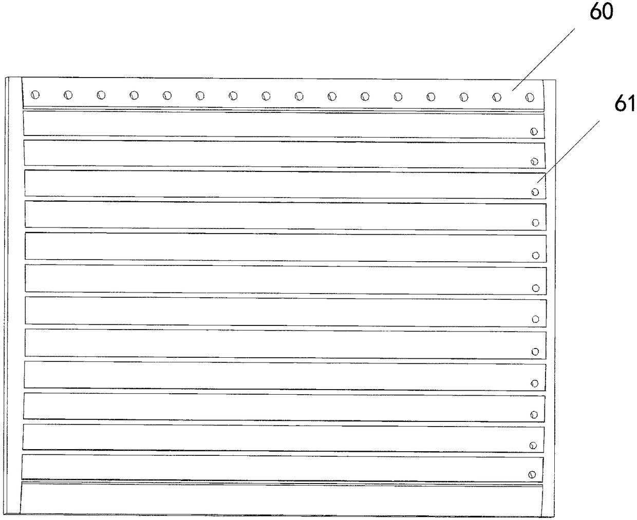
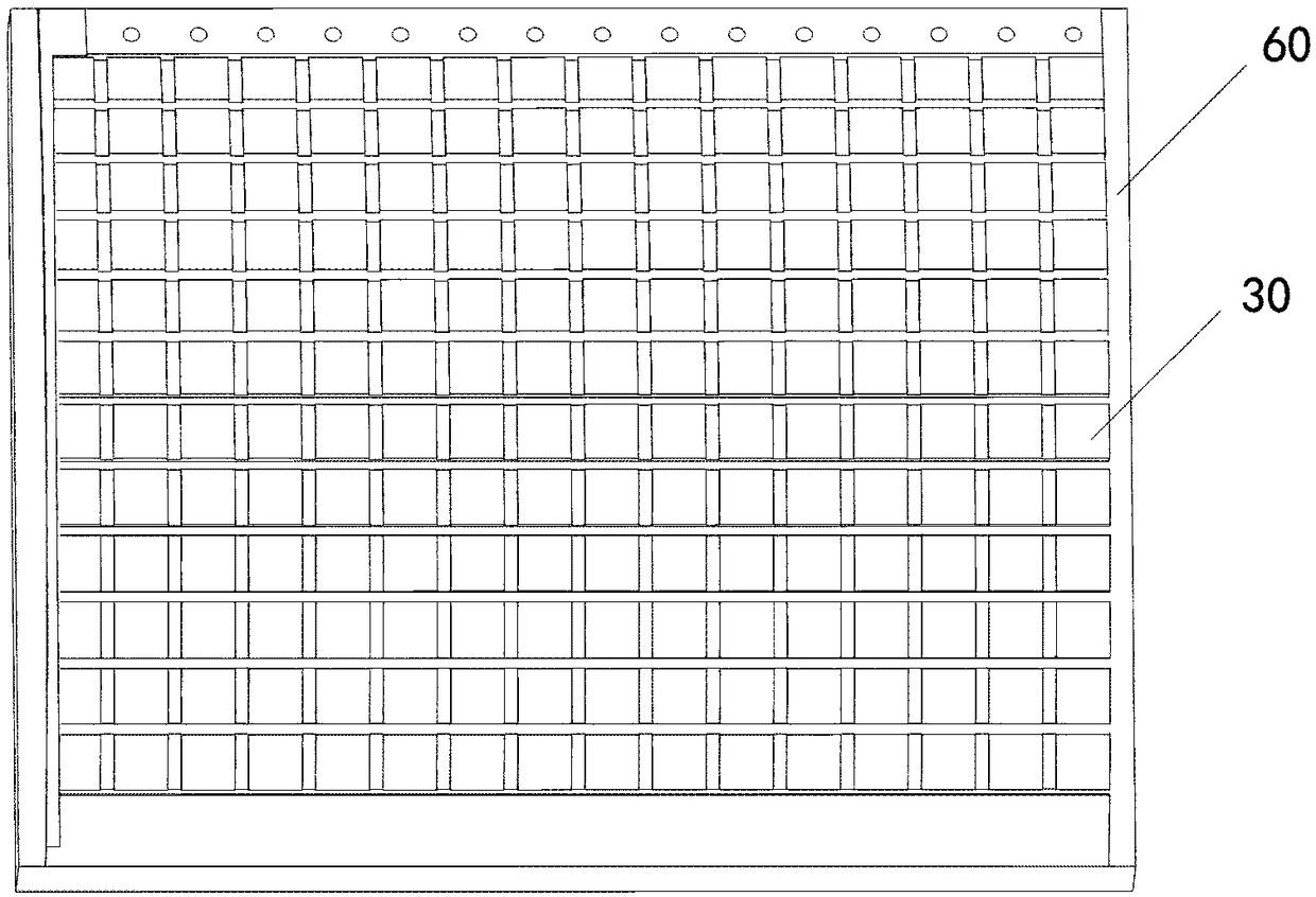
[0026] The palpation probe provided by the embodiment of the present invention includes a probe base, and a MEMS sensor array located on the probe base, wherein, as figure 1 As shown, the probe base includes a liner 60, and the surface of the liner 60 is provided with the same number of rubber strip grooves 61 as the number of MEMS sensor array rows; figure 2 As shown, each MEMS sensor in the MEMS sensor array 30 is aligned and arranged in the direction of row and column, and each row of MEMS sensors shares a low...


PUM


Abstract

The invention provides a palpation probe and a manufacturing method thereof. The palpation probe comprises a probe base, and an MEMS sensor array located on the probe base, wherein MEMS sensors in theMEMS sensor array are arranged in an aligned manner in lines and rows, and the MEMS sensors in each row share one lower electrode; the probe base comprises a lining, and adhesive tape grooves, of which the number is identical to the number of the lines of the MEMS sensor array, are formed in the surface of the lining; and the MEMS sensors in each row are adhesively connected to the lining throughfirst conducting adhesive tapes in the adhesive tape grooves. The palpation probe and the manufacturing method thereof provided by the invention has the beneficial effects that no circuit board is needed, so that connection wires between the sensors and the probe base on the palpation probe are reduced, and the palpation probe further achieves the advantages of compact structure, high conveniencein production, high stability and reliability in packaging structure, etc.

Description

technical field [0001] The invention relates to the technical field of medical devices, in particular to a palpation probe and a manufacturing method thereof. Background technique [0002] MEMS sensors can be used in breast palpation fusion ultrasound examination, and the connection and packaging between the MEMS sensor and the probe base will directly affect the difficulty of making the palpation probe, the reliability of the packaging, the anti-interference performance, and the signal-to-noise ratio. [0003] For example, when the MEMS sensor is packaged on the printed circuit board, a free-form dispensing method can be used. This method is to directly drop the liquid resin onto the position of the MEMS sensor and the gold wire on the printed circuit board. The resin flows freely during the process, which will form a drop-shaped envelope due to its own gravity and surface tension, but this encapsulation method cannot control the shape of the envelope well; The high-viscos...

Claims


Application Information

Patent Timeline
Patent Type & Authority Applications(China)
IPC IPC(8): B81B7/02B81C1/00A61B5/00
CPCA61B5/4312B81B7/02B81C1/00261B81C1/00269B81B2207/05B81B2201/02
Inventor 宋军华王洪超何常德王晓琴陈金胡志杰薄云峰薛黄琦何静
Owner BEIJING SINO CANBRIDGE MED TECH CO LTD
Learn More