
Annular circulation continuous vacuum coating device

A vacuum coating and ring-shaped technology, which is applied in vacuum evaporation coating, sputtering coating, ion implantation coating, etc., can solve the problem of increasing production cost, production time and production space, increasing the difficulty and cost of fault maintenance, and increasing the Problems such as the difficulty of workpiece transmission can achieve the effects of reducing equipment costs and maintenance costs, strong replaceability, and reducing the difficulty of machining

Active Publication Date: 2018-06-19
WENZHOU POLYTECHNIC
View PDF5 Cites 4 Cited by
  • Summary
  • Abstract
  • Description
  • Claims
  • Application Information

AI Technical Summary

Problems solved by technology

[0006] The structure of the linear continuous vacuum coating equipment is complicated. Multiple independent coating chambers need to be equipped with multiple high vacuum pump sets. The use of a large number of gates increases the production cost, production time, and production space. The complex equipment increases the difficulty of driving the workpiece to be coated. , the existence of multiple cavities also increases the difficulty and cost of fault maintenance in the production process, and the high threshold of linear continuous coating equipment greatly increases the cost of use for enterprises; for some small-sized workpieces, the current continuous processing requires A large amount of manpower loading and unloading makes it difficult to achieve continuous production

Method used

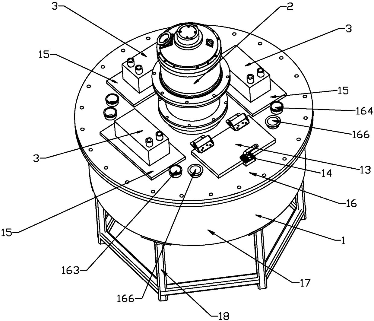
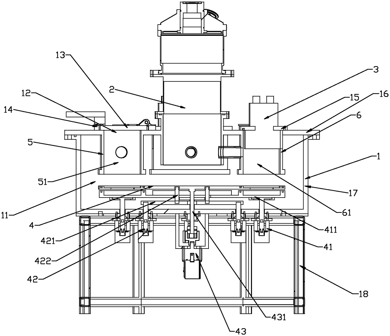
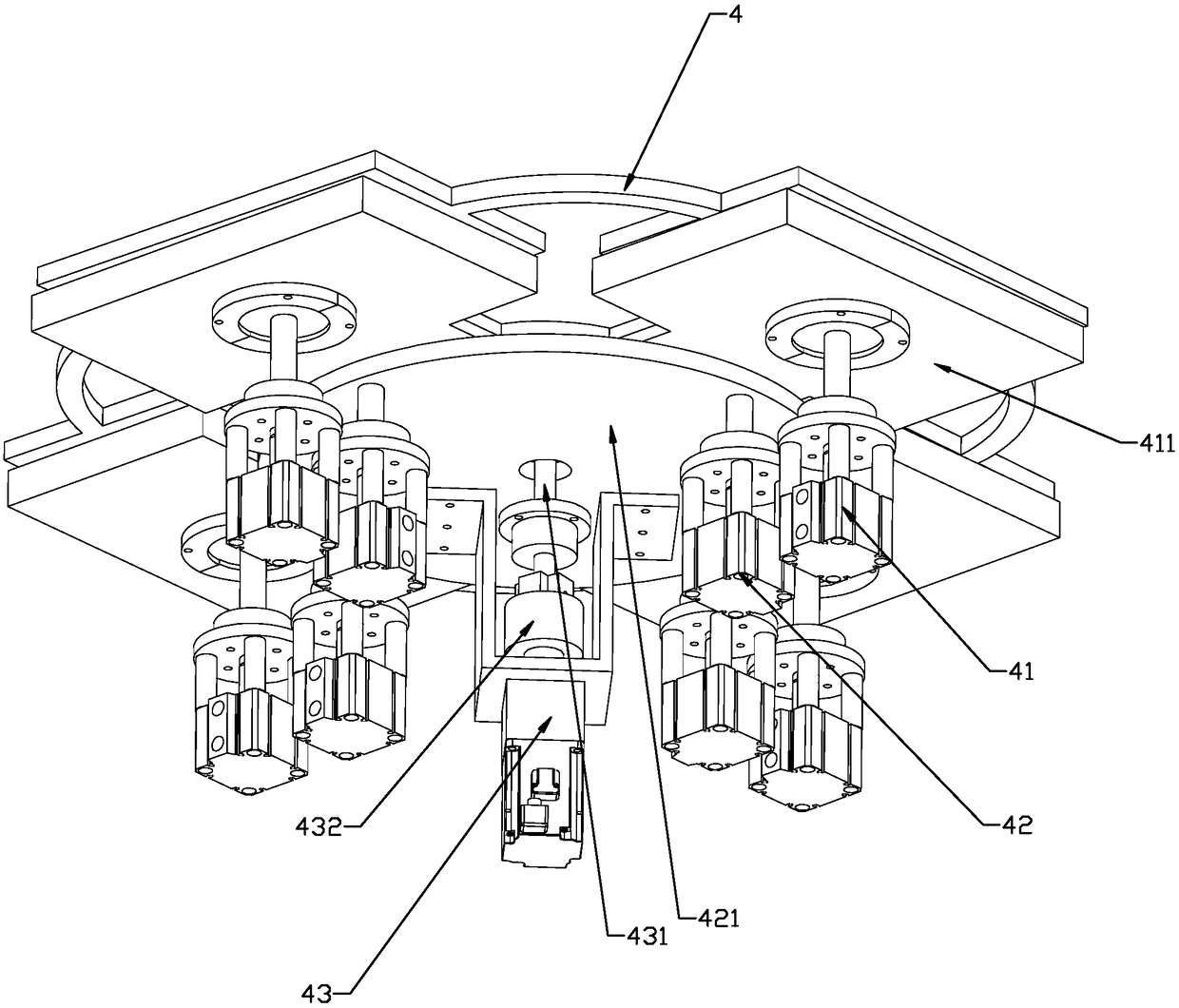

Image

  • Annular circulation continuous vacuum coating device
  • Annular circulation continuous vacuum coating device
  • Annular circulation continuous vacuum coating device

Examples


Embodiment Construction

[0028] In order to make the purpose, technical solutions and advantages of the present invention clearer, below in conjunction with embodiment and accompanying drawing, the present invention is described in further detail:

[0029] For the convenience of description, in the present invention, the obtaining of vacuum and restoring the atmosphere of the vacuum device are briefly described.

[0030] The vacuum device is welded and assembled with structural metal carbon steel, stainless steel, etc. In order to obtain the required vacuum degree, it is necessary to install an exhaust system on the vacuum device. Generally, the exhaust system is divided into two parts: a rough pumping system and a fine pumping system. The rough pumping system generally consists of a mechanical pump with a high pumping speed, a Roots pump, and a backing valve controlled by a cylinder and a solenoid valve. The fine pumping system includes one or more sets of high vacuum pumps and the backing pump unit o...


PUM


Abstract

The invention relates to an annular circulation continuous vacuum coating device which comprises a main cavity, a main vacuum system and coating technology assemblies, wherein the main cavity is provided with a main chamber and a feeding hole capable of being opened and closed; the annular circulation continuous vacuum coating device further comprises a rotary disc, a rotary disc lifting mechanism, a rotary disc rotating mechanism, a feeding chamber, a plurality of technological chambers and a feeding sub chamber vacuum system; the rotary disc rotating mechanism drives the rotary disc to rotate horizontally to transmit a to-be-coated workpiece among the feeding chamber and all technological chambers; the rotary disc lifting mechanism drives the rotary disc to go up and down to switch overthe feeding chamber and the technological chambers between the communicating state of the main chamber and the state of an independent vacuum chamber; the main vacuum system carries out vacuum treatment on the main chamber and all technological chambers; the feeding sub chamber vacuum system carries out vacuum treatment on the feeding chamber separately; and different coating technology assembliesare mounted on all technological sub cavities to realize different coating functions. The annular circulation continuous vacuum coating device can realize annular circulation continuous and low-costcoating production in the vacuum cavity.

Description

technical field [0001] The invention belongs to the technical field of vacuum coating equipment, in particular to an annular circulation continuous vacuum coating device. Background technique [0002] Existing vacuum coating equipment can be divided into single-type coating machines and continuous coating equipment according to the number of vacuum chambers in the vacuum equipment. [0003] The single-body coating machine usually consists of a vacuum chamber and an exhaust system. The vacuum coating process module is loaded on the chamber. When the required vacuum degree is reached, the required vacuum coating process module is activated to realize the processing of the material surface. , the single cavity leads to the need to open and close the door when the product is in and out, and the product cannot be continuously produced, which will greatly reduce the production efficiency and increase the labor cost, and the discontinuity of production will increase the product dif...

Claims


Application Information

Patent Timeline
IPC IPC(8): C23C14/56C23C16/54
CPCC23C14/568C23C16/54
Inventor 郎文昌
Owner WENZHOU POLYTECHNIC
Learn More