
Embroidery machine head and embroidery machine

An embroidery machine and machine head technology, applied in the field of embroidery machines, can solve problems such as excessive increase in motor and spindle speed, adjustment of the depth of engraving holes, and reduction of hole engraving efficiency, so as to facilitate internal structure layout, ensure stability, and ensure engraving. The effect of the hole effect

Pending Publication Date: 2018-06-19
ZHEJIANG XINSHENG SEWING EQUIP
View PDF0 Cites 2 Cited by
  • Summary
  • Abstract
  • Description
  • Claims
  • Application Information

AI Technical Summary

Problems solved by technology

Existing embroidery machine heads with both the engraving function and the embroidery function generally implement the two functions by setting up a motor to drive the main shaft to rotate, thereby realizing embroidery and engraving. The depth can be adjusted, that is, it can only adapt to one thickness of fabric, and the adaptability is single, and because the embroidery and the engraving are both driven by the same spindle, that is, the embroidery speed and the engraving speed are consistent, in order to ensure the normal operation of the embroidery, the motor cannot be used. and spindle speed increase too much, which reduces the engraving efficiency

Method used


Image

  • Embroidery machine head and embroidery machine
  • Embroidery machine head and embroidery machine
  • Embroidery machine head and embroidery machine

Examples


Embodiment Construction

[0032] The present invention will be further described in detail below in conjunction with the accompanying drawings and specific embodiments.

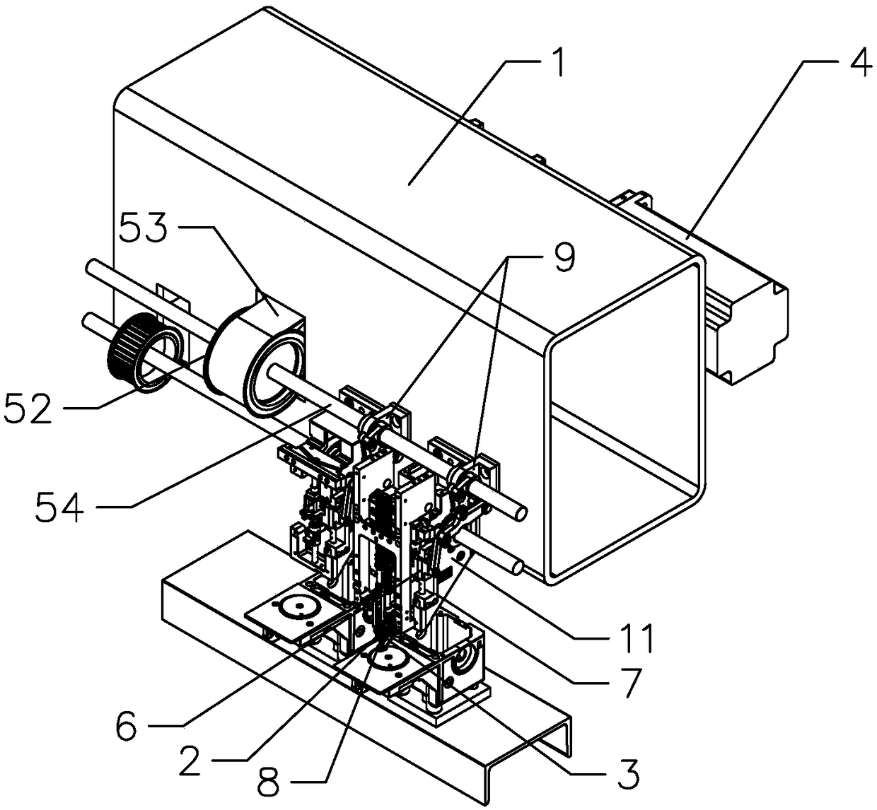
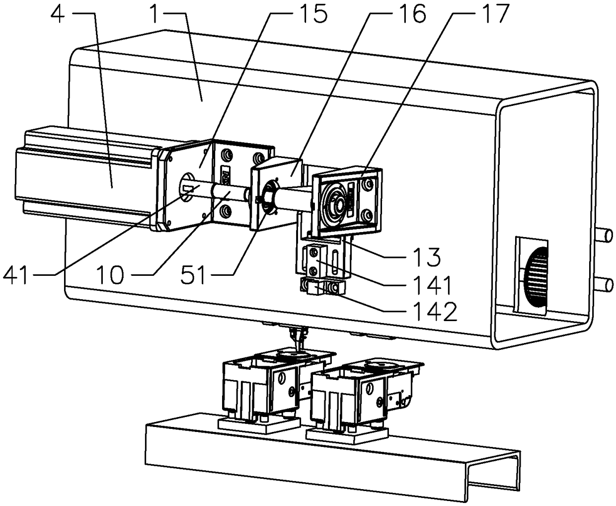
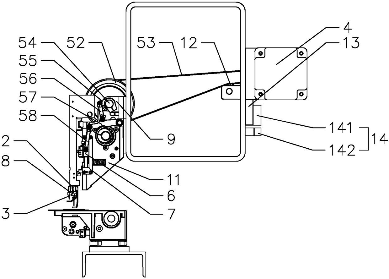
[0033] like Figures 1 to 4 As shown, the present invention provides a stable embroidery machine head, comprising a frame 1, a control panel, an embroidery device and a hole carving device installed on the frame 1, the embroidery device includes a needle bar and a needle head, and the hole carving device includes The carving knife bar 2 and the carving knife bar 3, the needle bar and the carving knife bar 2 are respectively driven by the embroidery driving system and the carving driving system which are independent of each other; of course, it can be understood that the embroidery device is a prior art, and the following is not correct The embroidery devices are described one by one.

[0034]In the present embodiment, the engraving drive system includes an independent engraving motor 4 and an engraving transmission mechanism connecti...


PUM


Abstract

The invention discloses an embroidery machine head and an embroidery machine. The embroidery machine head comprises a base frame, a control panel, an embroidery device and a stiletto device. The stiletto device comprises a stiletto cutter bar and a stiletto cutter; a needle bar and the stiletto cutter bar are driven by an independent embroidery driving system and a stiletto driving system respectively; the stiletto driving system comprises a stiletto motor and a stiletto transmission mechanism; the stiletto transmission mechanism comprises a first belt pulley, a second belt pulley, a stilettodriving shaft and a connecting rod assembly; The connecting rod assembly comprises a driving rod sleeved on the stiletto driving shaft, a first connecting rod connected to the driving rod, a three-eyeconnecting rod connected to the first connecting rod, and a second connecting rod connected with the three-eye connecting rod; The second connecting rod is connected with the stiletto cutter rod to drive the stiletto cutter to move up and down, so that the rotation angle of the stiletto motor can be controlled by the control panel to change the depth of the stiletto, adapt to the fabric of different thicknesses, enable the broader adaptability of the embroidery machine head; at the same time, the rotation speed of the stiletto motor can be improved to enhance the efficiency of hole engraving.

Description

technical field [0001] The invention relates to the technical field of embroidery machines, in particular to an embroidery machine head and an embroidery machine. Background technique [0002] At present, for the embroidery machine industry, with the improvement of product performance and the aesthetic requirements of fabrics, it is becoming more and more frequent to realize carving and embroidery on the same piece of fabric. Existing embroidery machine heads with both engraving and embroidery functions usually implement the two functions by setting up a motor to drive the main shaft to rotate, thereby realizing embroidery and engraving. The depth can be adjusted, that is, it can only adapt to one thickness of fabric, and the adaptability is single, and because the embroidery and the engraving are both driven by the same spindle, that is, the embroidery speed and the engraving speed are consistent, in order to ensure the normal operation of the embroidery, the motor cannot b...

Claims


Application Information

Patent Timeline
IPC IPC(8): D05C7/04D05C13/00D05C11/00
CPCD05C7/04D05C11/00D05C13/00
Inventor 王海江田桂郁
Owner ZHEJIANG XINSHENG SEWING EQUIP
Learn More