
Self-propelled slurry seal machine

A sealing machine and self-propelled technology, applied in roads, road repairs, roads, etc., can solve the problem of poor pavement flatness/aesthetics, poor versatility and applicability of storage boxes, and low utilization of the chassis of transport vehicles and other problems, to achieve the effect of good paving quality, high construction efficiency and good aesthetics

Pending Publication Date: 2018-06-19
河南省大道路业有限公司
View PDF9 Cites 1 Cited by
  • Summary
  • Abstract
  • Description
  • Claims
  • Application Information

AI Technical Summary

Problems solved by technology

[0003] However, at present, the paving device of the existing slurry sealing machine is generally dragged by the front vehicle through the drag chain, and the slurry mixture is directly sent into the paving device hopper by the discharge port after preparation and mixing, so that First, the speed of paving operation is affected by the vehicle in front, so it is difficult to achieve uniform paving operation, resulting in poor paving smoothness / aesthetics and affecting paving quality, and in order to meet the construction acceptance effect, repeated operations are required to complete , thus affecting the construction efficiency and prolonging the construction period
In addition, the storage box for the mixing device of the existing slurry sealer and the chassis of the transport vehicle are fixed and integrated, so the utilization rate of the chassis of the transport vehicle is low, and the versatility and applicability of the storage box are poor.

Method used


Image

  • Self-propelled slurry seal machine
  • Self-propelled slurry seal machine
  • Self-propelled slurry seal machine

Examples


Embodiment Construction

[0047] The technical solutions in the embodiments of the present invention will be clearly and completely described below in conjunction with the accompanying drawings in the present invention. Apparently, the described embodiments are only illustrative partial implementations of the present invention, and are not intended to limit the scope of the present invention. , any equivalent changes and modifications made by those skilled in the art without departing from the concepts and principles of the present invention shall fall within the protection scope of the present invention.

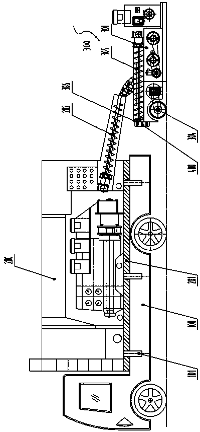
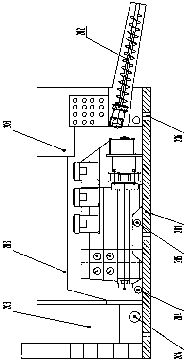
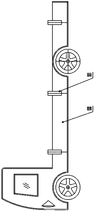
[0048] seefigure 1 , in the figure, the self-propelled slurry sealer of the present invention comprises a power transport vehicle chassis 100, a mixture stirring device 200 is installed on the power transport vehicle chassis, and a self-propelled micro-surface paving device 300 is provided at the rear of the power transport vehicle chassis . Wherein, the bottom plate 201 of the material storage box ...


PUM


Abstract

The invention relates to special equipment for road building and maintenance construction, in particular to a self-propelled slurry seal machine. The self-propelled slurry seal machine comprises a power transport vehicle chassis, a mixture stirring device and a micro-surfacing paving device. The micro-surfacing paving device comprises a paving box, a paving hopper arranged at the top of the pavingbox, a distribution mechanism arranged in the paving box, sliding rails arranged at the bottom of the paving box and a power transmission mechanism. The micro-surfacing paving device further comprises a self-walking mechanism and a material propelling mechanism, the material propelling mechanism is arranged on a carrier platform arranged at the top of the self-walking mechanism, the paving box isfixedly connected to the rear portion of the carrier platform, a feeding port in the front end of the material propelling mechanism is located under a discharging port formed in the mixture stirringdevice, and a discharging port in the rear end of the material propelling mechanism is located over an inlet of the paving hopper. The discharging port of the mixture stirring device is a lengthened discharging port. The paving quality is good after construction is conducted one time, construction operation efficiency is high, so that a construction period is greatly shortened, and the machine issuitable for being implemented and popularized.

Description

technical field [0001] The invention relates to a special equipment for road construction and road maintenance, in particular to a self-propelled slurry sealing machine. Background technique [0002] The slurry sealing machine is a special equipment for completing the slurry sealing construction. The early slurry sealing equipment used cement concrete mixer to mix the slurry mixture, then transported it to the site by tank truck, and spread it manually. shop. After the 1960s, European and American countries began to develop slurry sealers. It can integrate the preparation, mixing and paving of slurry mixture, so that the construction method of slurry seal layer has a rapid development, making this construction method truly economical, effective, fast and reliable. Due to the continuous emergence of new slurry sealers, the application of this technology in the world has been further promoted. Since 1989, many domestic provinces and cities have introduced advanced slurry se...

Claims


Application Information

Patent Timeline
Patent Type & Authority Applications(China)
IPC IPC(8): E01C19/45
CPCE01C19/45
Inventor 李煜焱段瑞卿徐巍巍翟书永轩元伟
Owner 河南省大道路业有限公司
Learn More