Supercharge Your Innovation With Domain-Expert AI Agents!

Metal wire meter resistance continuous precision test device and method

A testing device and meter resistance technology, applied in the direction of measuring device, measuring resistance/reactance/impedance, measuring electrical variables, etc., can solve the problems of wire surface indentation, large error, complicated process, etc., and achieve the effect of ensuring uniformity

Active Publication Date: 2018-06-19
CHONGQING MATERIALS RES INST
View PDF9 Cites 5 Cited by
  • Summary
  • Abstract
  • Description
  • Claims
  • Application Information

AI Technical Summary

Problems solved by technology

For high-precision resistance wires used in aviation, aerospace and other fields, the resistance accuracy is required to be 1% or even lower. Conventional methods cannot accurately test the resistance uniformity due to excessive errors.
[0003] There are related reports in China for testing the resistance of resistance wire meters. For example, Zhou Dan et al. have prepared a fixture for electric heating wire meter resistance test device, but the fixture can only provide a single clamping test, and the wire will be damaged after the test. Indentation on the surface, etc., low test efficiency; Chai Zhiqing used the "voltage-current method" to prepare the continuous meter resistance test device. This method is controlled by a single-chip microcomputer, and the process is complicated. Due to digital-to-analog conversion and limited precision of components, the accuracy can only reach ±2 %, unable to meet the requirements of high-precision continuous meter resistance test

Method used


Image

  • Metal wire meter resistance continuous precision test device and method
  • Metal wire meter resistance continuous precision test device and method
  • Metal wire meter resistance continuous precision test device and method

Examples


Embodiment Construction

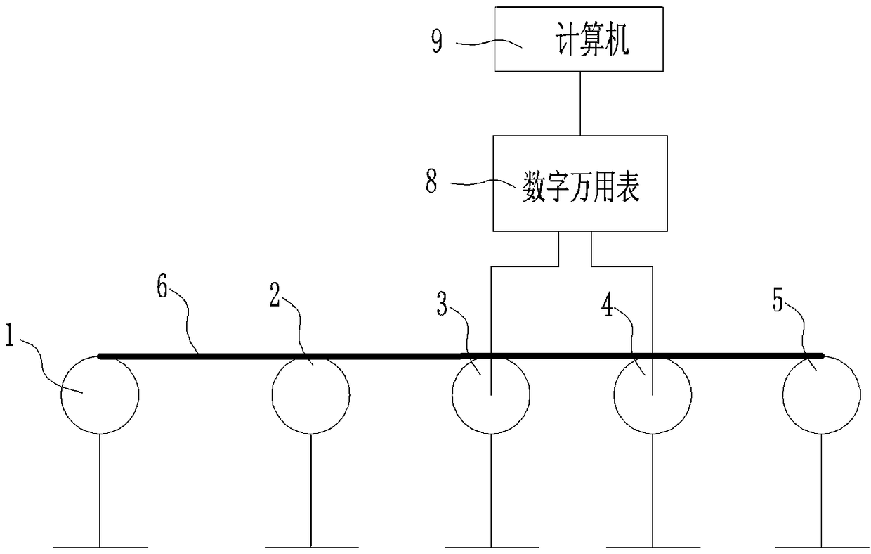
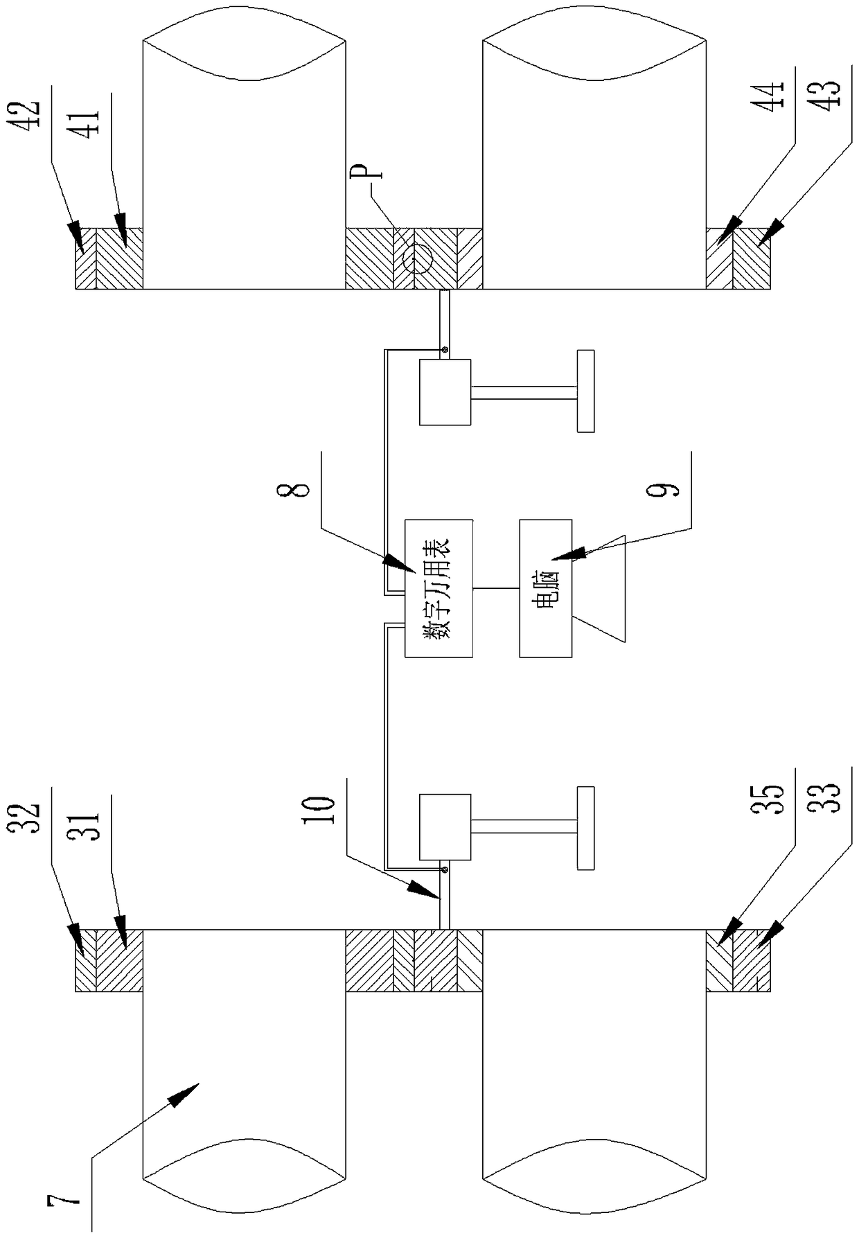
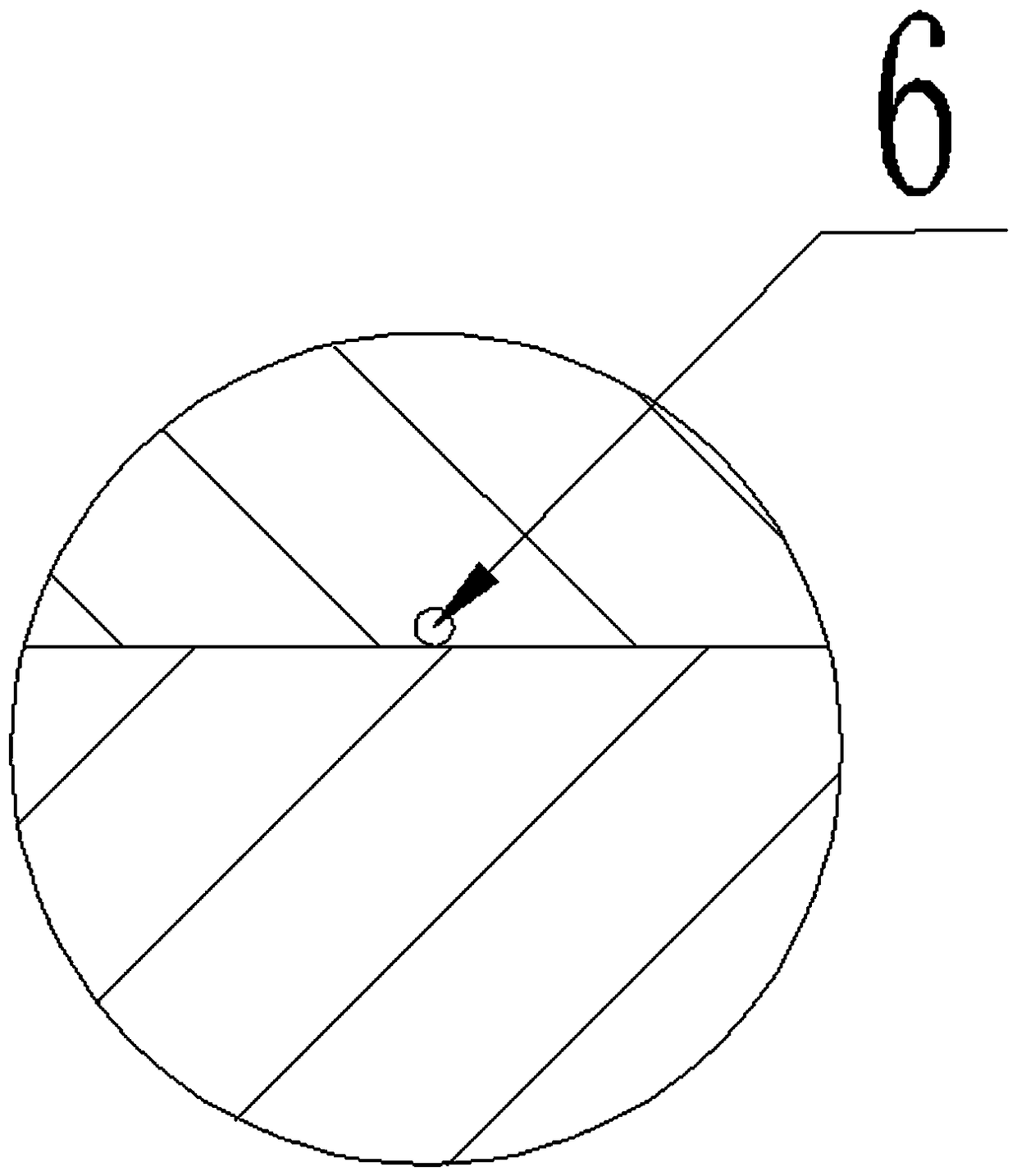
[0037] see Figure 1 to Figure 6 , a continuous precision testing device for the resistance of a metal wire meter, comprising a wire pay-off device 1 and a wire take-up device 5, a resistance collection device is arranged between the wire release device 1 and the wire take-up device 5, and the resistance collection device includes a The first upper and lower roller device 3 and the second upper and lower roller device 4 arranged at intervals in the length direction of the wire to be measured, the upper and lower rollers of the first upper and lower roller device 3 and the second upper and lower roller device 4 are respectively connected to the corresponding rotating shaft 7 Circumferentially fixedly connected and supported on the corresponding rotating shaft 7, the rotating shaft 7 is connected with the driving device, so that the driving device drives the upper roller and the lower roller to rotate; the lower roller of the first upper and lower roller device 3 includes the fir...


PUM


Abstract

The invention relates to a metal wire meter resistance continuous precision test device and method. The device comprises an unspooling device and a spooling device, wherein a resistance acquisition device is arranged between the unspooling device and the spooling device; a plurality of test insection stripes are uniformly distributed on the circumference of the circumferential outer wall of a first lower roller conductive skeleton of a lower roller of a first upper-lower roller device of the resistance acquisition device for sequentially contacting a to-be-tested wire during a rotation process; the circumferential outer wall of the first lower roller conductive skeleton is fixed with a first lower roller elastic sleeve; a first insulation layer is arranged between the first lower roller conductive skeleton and a rotation shaft; the lower roller of a second upper-lower roller device comprises a second lower roller conductive skeleton for contacting a to-be-tested wire, and a second insulation layer is arranged between the second lower roller conductive skeleton and the rotation shaft; and both the first lower roller conductive skeleton and the second lower roller conductive skeletonare connected with a resistance measurement device through conductive test heads. Continuous test on a whole coil of wire meter resistance can be realized, uniformity of the whole wire meter resistance is ensured, and the precision is high.

Description

technical field [0001] The invention relates to the field of testing the resistance of metal wire meters, in particular to a continuous precision testing device and a testing method for the resistance of metal wire meters. Background technique [0002] For commonly used resistance wires such as nickel-chromium wire, iron-chromium-aluminum wire, tungsten-aluminum wire, etc., in order to ensure the stability of its heating power and product interchangeability, it is necessary to test its meter resistance. For ultra-fine resistance wire, in order to accurately measure its diameter, there is a method of calculating the wire diameter by weight, or calculating its diameter by testing the resistance value. For high-precision resistance wires used in aviation, aerospace and other fields, the resistance accuracy is required to be 1% or even lower. Conventional methods cannot accurately test the resistance uniformity due to excessive errors. [0003] There are related reports in Chin...

Claims


Application Information

Patent Timeline
Patent Type & Authority Applications(China)
IPC IPC(8): G01R27/02
CPCG01R27/02
Inventor 薄新维刘奇王小宇蒋春东刘成超王焱辉何浩然陈德茂
Owner CHONGQING MATERIALS RES INST
Features
  • R&D
  • Intellectual Property
  • Life Sciences
  • Materials
  • Tech Scout
  • Unparalleled Data Quality
  • Higher Quality Content
  • 60% Fewer Hallucinations
Learn More