Supercharge Your Innovation With Domain-Expert AI Agents!

Metal wire meter resistance continuous precision testing device and method

A test device, meter resistance technology, applied in the direction of measuring device, measuring resistance/reactance/impedance, measuring electrical variables, etc., can solve the problems of wire surface indentation, large error, complicated process, etc., and achieve the effect of ensuring uniformity

Active Publication Date: 2020-10-09
CHONGQING MATERIALS RES INST
View PDF9 Cites 0 Cited by
  • Summary
  • Abstract
  • Description
  • Claims
  • Application Information

AI Technical Summary

Problems solved by technology

For high-precision resistance wires used in aviation, aerospace and other fields, the resistance accuracy is required to be 1% or even lower. Conventional methods cannot accurately test the resistance uniformity due to excessive errors.
[0003] There are related reports in China for testing the resistance of resistance wire meters. For example, Zhou Dan et al. have prepared a fixture for electric heating wire meter resistance test device, but the fixture can only provide a single clamping test, and the wire will be damaged after the test. Indentation on the surface, etc., low test efficiency; Chai Zhiqing used the "voltage-current method" to prepare the continuous meter resistance test device. This method is controlled by a single-chip microcomputer, and the process is complicated. Due to digital-to-analog conversion and limited precision of components, the accuracy can only reach ±2 %, unable to meet the requirements of high-precision continuous meter resistance test

Method used


Image

  • Metal wire meter resistance continuous precision testing device and method
  • Metal wire meter resistance continuous precision testing device and method
  • Metal wire meter resistance continuous precision testing device and method

Examples


Embodiment Construction

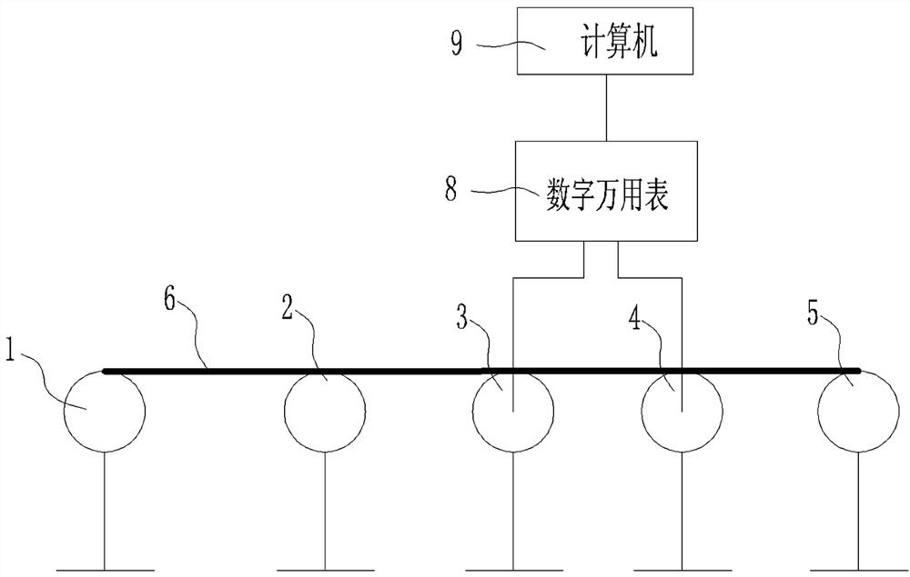
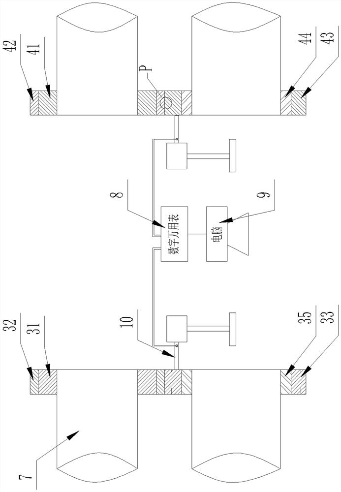
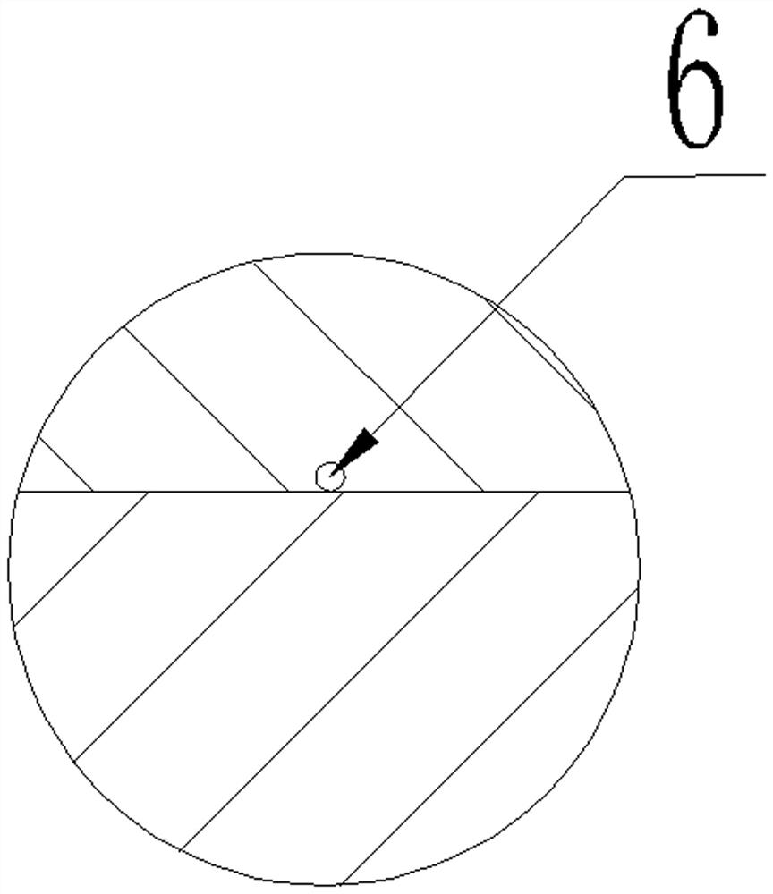
[0037] See Figure 1 to Figure 6 , A metal wire meter resistance continuous precision test device, comprising a wire pay-off device 1 and a wire take-up device 5. A resistance collection device is arranged between the wire take-up device 1 and the wire take-up device 5, and the resistance collection device includes A first upper and lower roller device 3 and a second upper and lower roller device 4 are arranged at intervals in the length direction of the wire to be measured. The upper roller and the lower roller of the first upper and lower roller devices 3 and the second upper and lower roller devices 4 respectively correspond to the corresponding rotating shafts 7 Circumferentially fixedly connected and supported on the corresponding rotating shaft 7, the rotating shaft 7 is connected with the driving device, so that the driving device drives the upper roller and the lower roller to rotate; the lower roller of the first upper and lower roller device 3 includes a first lower ro...


PUM


Abstract

The invention relates to a metal wire meter resistance continuous precision test device and method. The device comprises an unspooling device and a spooling device, wherein a resistance acquisition device is arranged between the unspooling device and the spooling device; a plurality of test insection stripes are uniformly distributed on the circumference of the circumferential outer wall of a first lower roller conductive skeleton of a lower roller of a first upper-lower roller device of the resistance acquisition device for sequentially contacting a to-be-tested wire during a rotation process; the circumferential outer wall of the first lower roller conductive skeleton is fixed with a first lower roller elastic sleeve; a first insulation layer is arranged between the first lower roller conductive skeleton and a rotation shaft; the lower roller of a second upper-lower roller device comprises a second lower roller conductive skeleton for contacting a to-be-tested wire, and a second insulation layer is arranged between the second lower roller conductive skeleton and the rotation shaft; and both the first lower roller conductive skeleton and the second lower roller conductive skeletonare connected with a resistance measurement device through conductive test heads. Continuous test on a whole coil of wire meter resistance can be realized, uniformity of the whole wire meter resistance is ensured, and the precision is high.

Description

Technical field [0001] The invention relates to the field of metal wire meter resistance testing, in particular to a continuous precision test device and test method for metal wire meter resistance. Background technique [0002] For commonly used resistance wires such as nickel-chromium wire, iron-chromium-aluminum wire, tungsten-aluminum wire, etc., in order to ensure stable heating power and product interchangeability, it is necessary to test its resistance. For extremely thin resistance wires, in order to accurately measure their diameter, there are methods to calculate the wire diameter by weight, or to calculate the diameter by testing the resistance value. For high-precision resistance wires used in aviation, aerospace and other fields, the resistance accuracy is required to be 1% or less. Conventional methods cannot accurately test the resistance uniformity due to excessive errors. [0003] For testing the resistance of the resistance wire, there are related reports in Chin...

Claims


Application Information

Patent Timeline
Patent Type & Authority Patents(China)
IPC IPC(8): G01R27/02
CPCG01R27/02
Inventor 薄新维刘奇王小宇蒋春东刘成超王焱辉何浩然陈德茂
Owner CHONGQING MATERIALS RES INST
Features
  • R&D
  • Intellectual Property
  • Life Sciences
  • Materials
  • Tech Scout
  • Unparalleled Data Quality
  • Higher Quality Content
  • 60% Fewer Hallucinations
Learn More