
High-precision constant power DC power supply

Inactive Publication Date: 2018-06-19
广东恒惠源电子有限公司
View PDF2 Cites 5 Cited by
  • Summary
  • Abstract
  • Description
  • Claims
  • Application Information

AI Technical Summary

Problems solved by technology

[0002] In the electronic laboratory, due to the need to test a variety of different products, the power supply usually selected needs to have a certain margin, because it is usually difficult to predict the various test requirements that may appear in the future
Therefore, the current market situation is that many laboratories must prepare multiple types of power supplies to meet testing requirements, because conventional DC power supplies include linear power supplies and switching power supplies, and linear power supplies use low-frequency isolation transformers and linear adjustment circuits. Low power, high control precision, but low efficiency and large volume. The switching power supply uses a high-frequency transformer, and the switch adjustment circuit has the characteristics of high efficiency, small size, but large output ripple and low control precision. Its power output The capacity is proportional to its core cross-sectional area and the area of ​​the winding window. For a certain transformer, the maximum power it transfers is limited by the effective cross-sectional area of ​​the magnetic core and the area of ​​the winding window. This maximum power limits its The product of output voltage and current, if a larger output current is required under a certain output voltage, a larger transformer is required, and the replacement of a larger transformer requires higher costs and requires a larger chassis to place it, that is, it takes up the experimental space. Room space is wasted, testing cost is wasted, and wiring trouble is caused, and the control accuracy is not high, because for engineers, it means that every time a product is tested, a power supply needs to be replaced
Generally speaking, the defects of the narrow voltage / current range range of this kind of power supply products on the market in a certain power range cause customers to need to purchase multiple power supplies with different powers to meet the test requirements, resulting in increased cost of purchasing power supplies and waste of resources , and it is very inconvenient to frequently replace the power supply

Method used


Image

  • High-precision constant power DC power supply
  • High-precision constant power DC power supply

Examples


Embodiment Construction

[0010] The following will clearly and completely describe the technical solutions in the embodiments of the present invention with reference to the accompanying drawings in the embodiments of the present invention. Obviously, the described embodiments are only some, not all, embodiments of the present invention. Based on the embodiments of the present invention, all other embodiments obtained by persons of ordinary skill in the art without making creative efforts belong to the protection scope of the present invention.

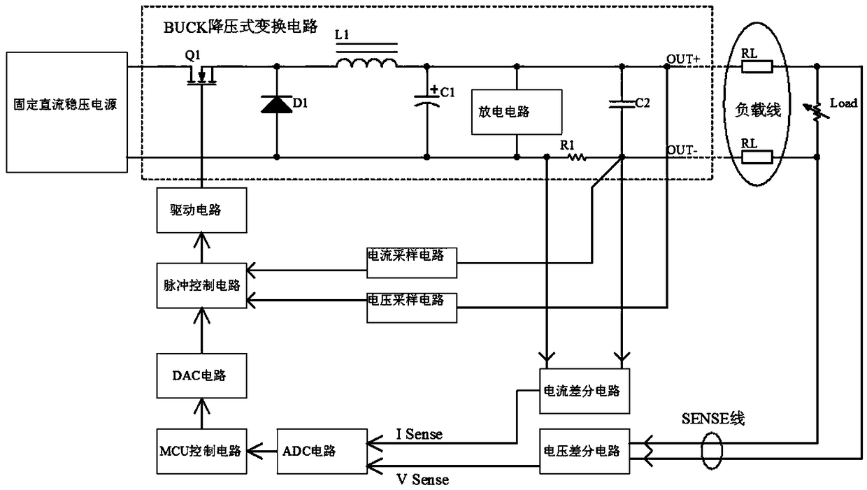
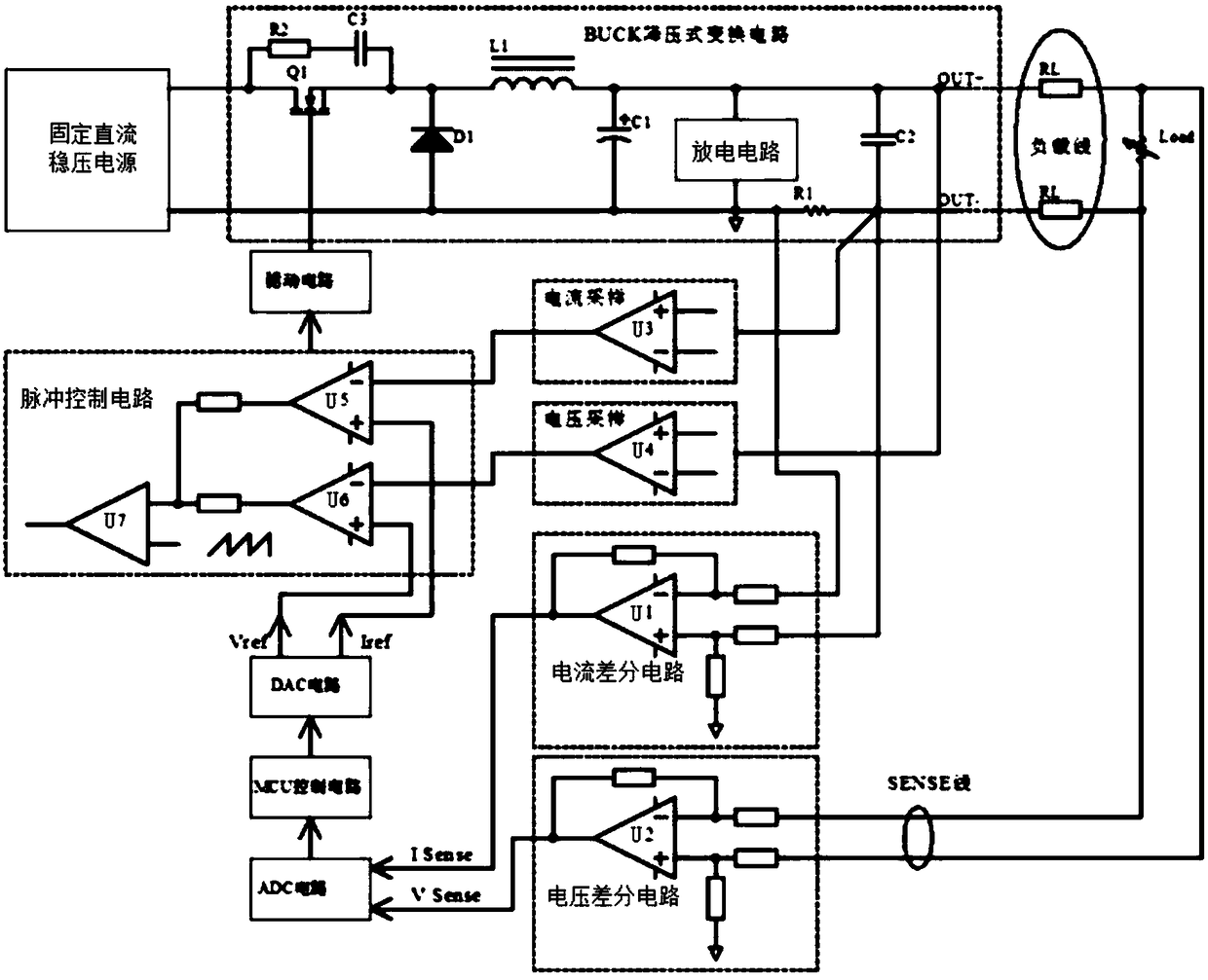
[0011] see Figure 1-2 , a high-precision constant power DC power supply, including a fixed DC regulated power supply, BUCK step-down conversion circuit, discharge circuit, drive circuit, pulse control circuit, current sampling circuit, voltage sampling circuit, MCU control circuit, ADC circuit, DAC circuit, current differential circuit and voltage differential circuit.

[0012] The output positive pole of the fixed DC stabilized power supply is connected to ...


PUM


Abstract

The invention discloses a high-precision constant power DC power supply including a fixed DC voltage stabilization power supply, a BUCK conversion circuit, a discharging circuit, a driving circuit, apulse control circuit, a current sampling circuit, a voltage sampling circuit, an MCU control circuit, an ADC circuit, a DAC circuit, a current differential circuit and a voltage differential circuit.The constant power output can be achieved, the output characteristics of high voltage and low current or high current and low voltage can be achieved, the ADC and DAC can be used to achieve high-precision output collection and high-precision control output, and the high-precision requirements of power remote end load adjustment can be satisfied at the same time.

Description

technical field [0001] The invention relates to a direct current power supply, in particular to a high-precision constant power direct current power supply. Background technique [0002] In the electronic laboratory, due to the need to test a variety of different products, the power supply usually selected needs to have a certain margin, because it is usually difficult to predict the various test requirements that may appear in the future. Therefore, the current market situation is that many laboratories must prepare multiple types of power supplies to meet testing requirements, because conventional DC power supplies include linear power supplies and switching power supplies, and linear power supplies use low-frequency isolation transformers and linear adjustment circuits. Low power, high control precision, but low efficiency and large volume. The switching power supply uses a high-frequency transformer, and the switch adjustment circuit has the characteristics of high effic...

Claims


Application Information

Patent Timeline
IPC IPC(8): H02M3/157
Inventor 胡升平
Owner 广东恒惠源电子有限公司
Learn More